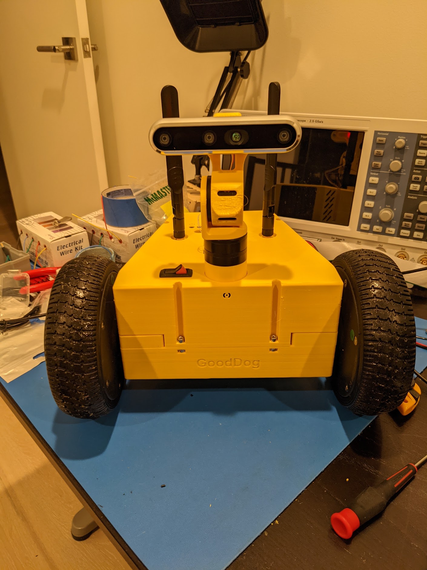
The new gimbal-based pan-tilt module allows you to mount an Intel RealSense camera to the robot, and have that camera be able to look in two-axes. The gimbal based motors don’t have any gearboxes, which brings some pros and cons.
Pros:
- Quiet, repeatable operation, with no wear-and-tear
- Low backlash operation
- +/- 35 degrees of operation in each axis
- ROS Drivers
Cons:
- Low torque, requiring you to balance the center of gravity
- More parts and wiring
The cost is actually similar to a servo based pan-tilt head, if you are using nicer Dynamixel servos.
The tilt motor in this configuration is in an unstable equilibrium, and in fact, it will draw more current when the angle is greater than zero. However, in a practical setting, this is ~350ma at most at the largest angles, and there are mechanical endstops to prevent it from tilting so far that it can’t return back to center under motor power.
Update Dec 2022: I ended up swapping the RealSense for a NileCAM21. The RealSense has a number of issues, including very bad performance in sunlight (everything turns purple and blurs), and bad performance in low light (like a very old digital camera), and the USB connectivity was difficult to deal with. The NileCAM21 is decent on those fronts, and uses FAKRA coax connectors, letting you use a thin and flexible cable.
Everything else in the design has stayed the same, but I have a modified version of the head piece which can mount the new camera.
As you can see, the head can move rapidly, smoothly, and is nearly completely silent. And, there are few parts to wear down over time, leading to consistent operation over a variety of conditions and a long duration of operation.
Component List
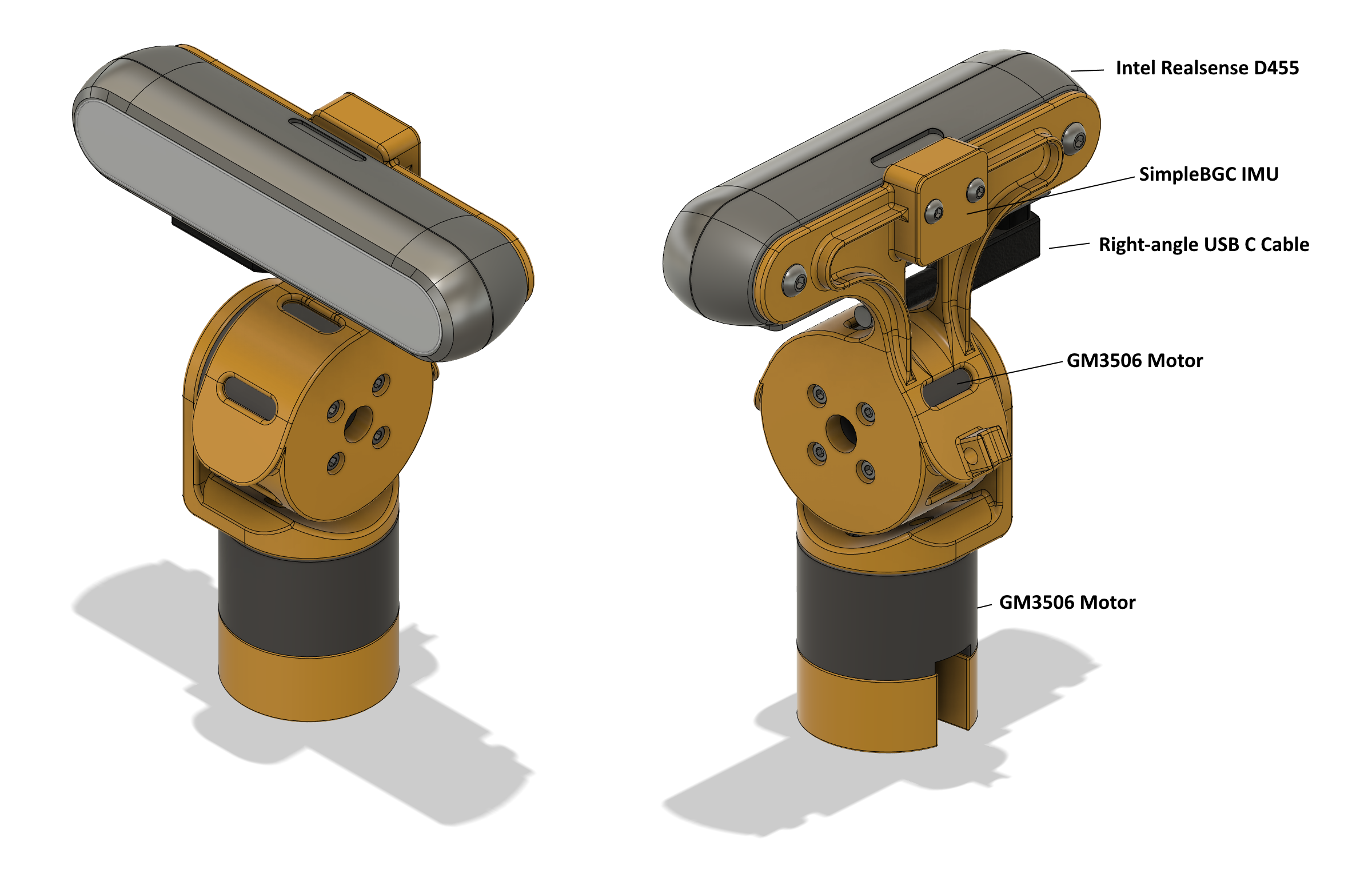
- 2 X GM3506 Motor w/ AS5048A Encoder
- BaseCam SimpleBGC 32-bit Tiny Rev. C
- 2x9 Crimp Connector Housing
- Female Crimp terminals
- Intel RealSense D455 Camera
- Right-angle USB C 3.1 Cable
- Right-angle USB C adapters
Encoder Wiring
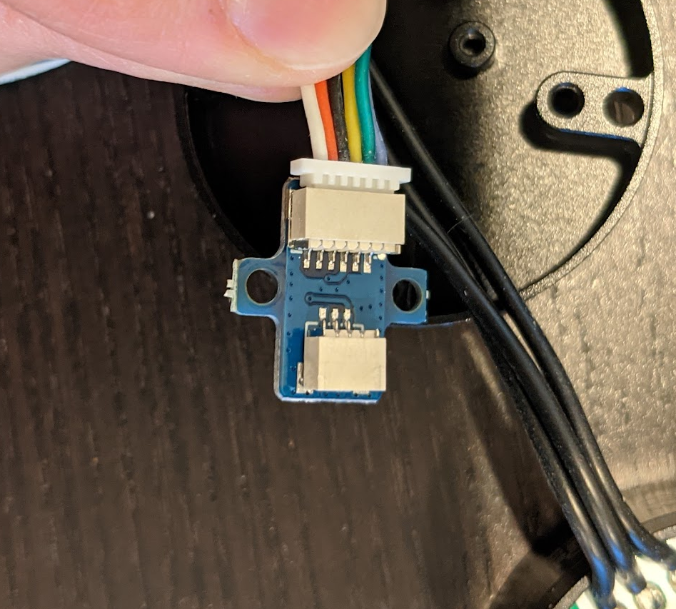
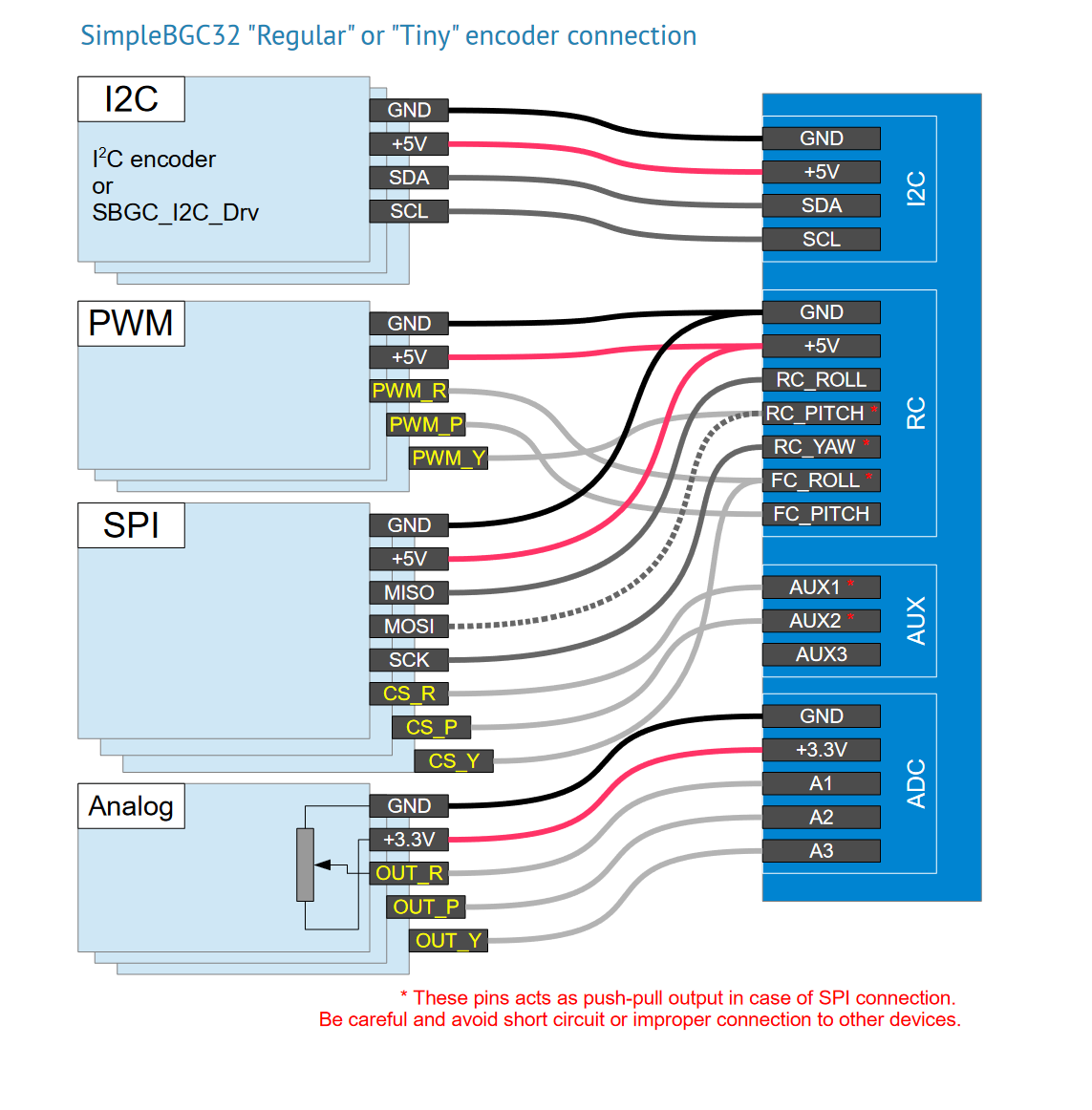
The AS5048A Encoder connects to the SimpleBGC using a SPI interface. That means 6 connections per board: 3.3V, Ground, MISO, MOSI, CLK, and CS. Each of the two encoders will share most of those connections, and only have a separate CS line.
The first thing you’ll need to do, is open up the encoder, and replace the 3-pin cable with the full 6 pin SPI-cable. Both cables should be included with the motor, and it’s just a matter of opening the case and replacing it.
Next, you’ll have to attach female crimp connectors to all of the pins coming from the encoder. Double up the 3.3V, Ground, MISO, MOSI, CLK connections from both encoders into one pin each, and then separate out the CS line from each encoder on it’s own pin.
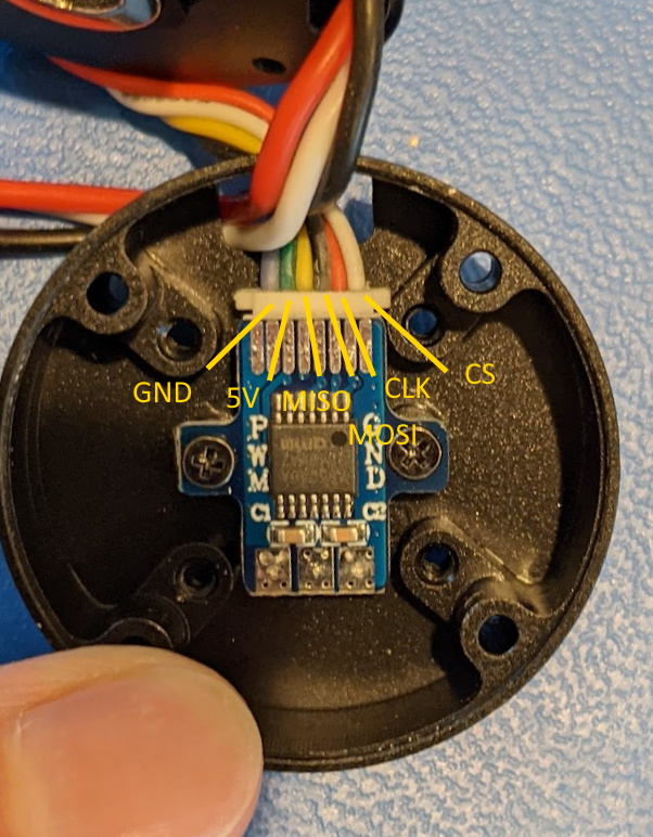
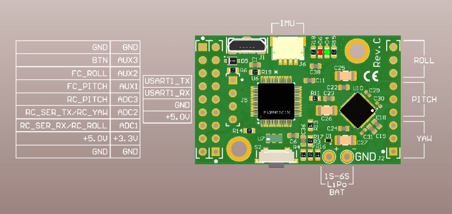
So, what you need to do is map the following pins, reading left to right
- GND ⇨ GND
- 5V ⇨ 5V
- MISO ⇨ RC_SER_RX/RC_ROLL
- MOSI ⇨ RC_PITCH
- CLK ⇨ RC_SER_TX/RC_YAW
- CS (pitch motor) ⇨ AUX2
- CS (yaw motor) ⇨ FC_ROLL
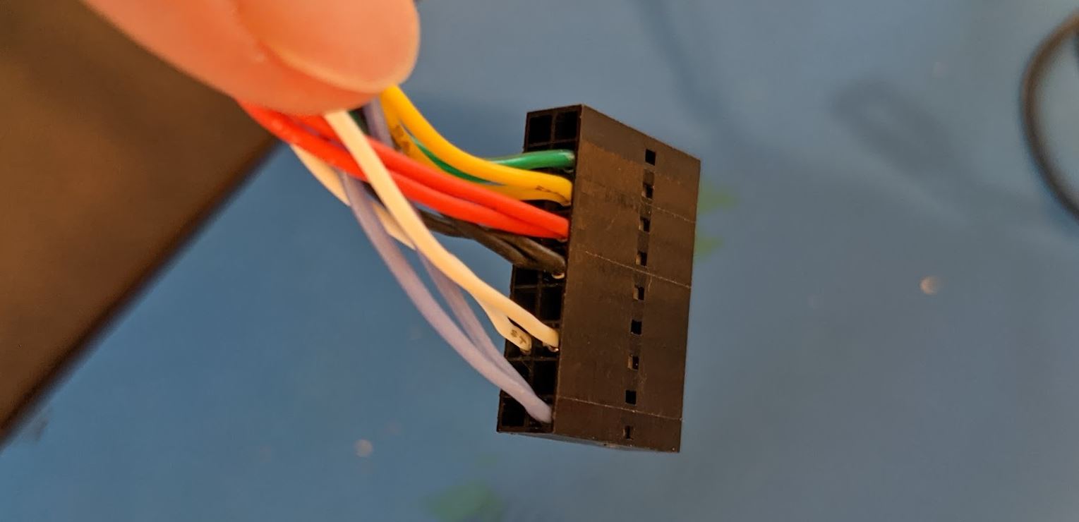
I used a 9x2 Molex SL female header to attach the encoders to the Simple BGC.
Mechanical Setup
To assemble the pan-tilt module, first connect the SPI cables to the encoders and prepare the harness to connect that to the SimpleBGC board as in the section above. You may want to assemble the final 9x2 pin header with the wires already going through the hole in the top of the robot case, so that you don’t want to disconnect anything later.
Next, you’ll want to print and assemble the 3D-printed plastic components.
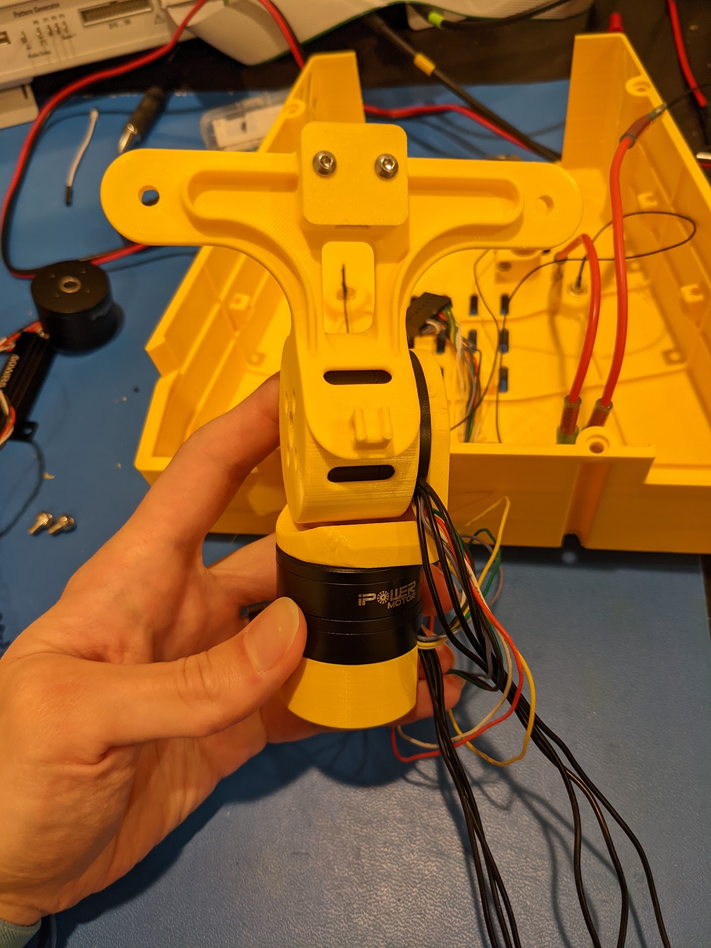
The GM3506 motors mount with M2.5 screws. First, screw in the bottom “head base” to the GM3506 motor, and then attach the first motor to the “head base” and the “middle bracket”. You’ll want to route the motor cables for the bottom motor out the base. I would suggest to keep the bundles for the SPI/Encoder wires and the motor power connections separate as best as possible to avoid EMI.
Then, take the second motor, and attach it to the “Camera bracket”, making sure the wires come out the back.
Attach the IMU to the camera bracket, this part uses M3 hex-cap screws, and route it’s cable out the back end. You can use a small zip-tie to clip the cable to the plastic bracket.
Finally, you can mount the Intel Realsense D455 using two M4x8 screws. The actual Head base connects with two M3x10 bolts, with the threads directly 3D printed. It’s actually quite strong: neat!
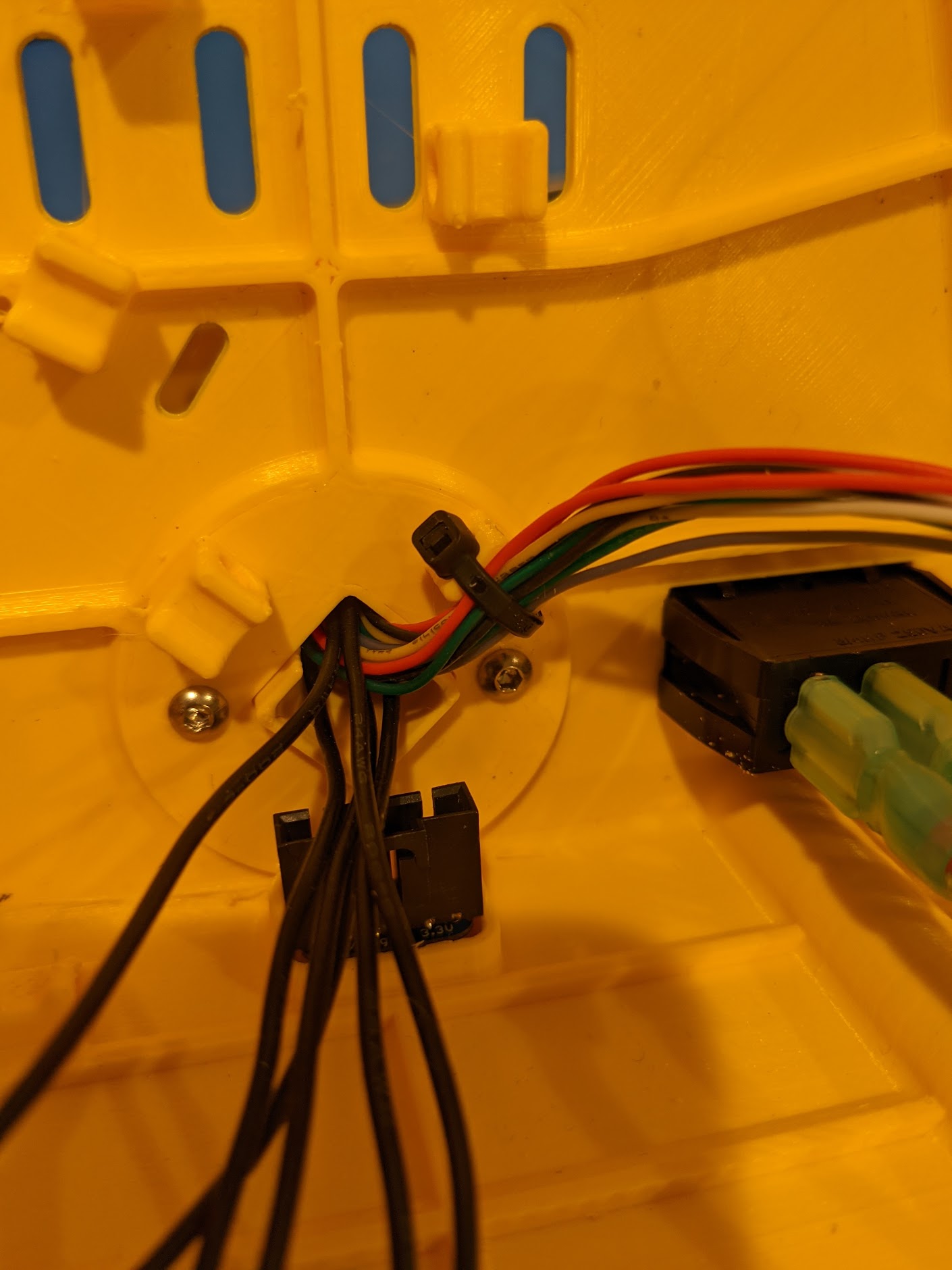
Once you get this far, you’ll need to start using the zip tie posts and some small zip ties to keep the wiring clean. The first versions I built didn’t worry about this, and there were constant EMI issues, so take good care, and be sure to keep your wires cut down as short as possible.
You’ll also want to take the other end of the IMU cable, and pass it through the provided opening in the case.
The final wiring is as shown below. Notice how the black power wires from the motors are physically separate from everything else. The power wires for the simple BGC are soldered on, crimped with PowerPole 15 connectors, and then routed down the case directly to the terminal block. If you are extra-paranoid about EMI, like I am, then you can also route the motor power cables through some small ferrites.
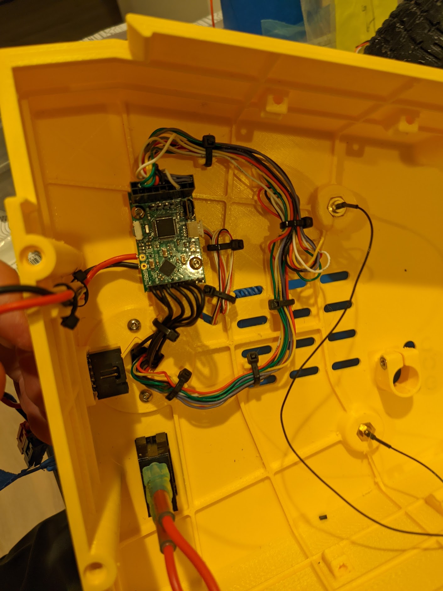
You can then route the USB-C cable for the Intel RealSense down to the Jetson Xavier inside the case. I recommend to use two zip ties to as shown in the image below to act as a strain relief for the USB cable. Also, please check the linked cables in the BOM above, they were the ones that worked perfectly for me, after trying many varieties. You’ll need a right-angle connection for the camera, but some RealSense boards are actually sensitive to the polarity of the connection! So, with a double-right-angle cable you can always make it work. And, you’ll need a small adapter to have enough space to plug everything into the Jetson itself.
How to configure the camera
Once you have everything working, you will need to connect a USB cable from your computer, to the SimpleBGC board, and get the SimpleBGC setup utility working.
- Start with the Encoders tab
- Enable the encoders AS5048A in SPI Mode on the Pitch and Yaw axes
- Enable the “skip autodetect” for the encoders
- Go the Hardware tab
- Roll disabled
- Pitch and Yaw enabled, inverted, Num Poles = 22
- Set the power to ~75
- Axis TOP = Y
- Axis RIGHT = X
- Go to the Stabilization tab
- Start with the following PID parameters, to be tuned more later
- Pitch - P10, I5, D9, Outer P 150
- Yaw - P9, I5, D16, Outer P 150
- Low pass filter 400 Hz on both Pitch and Yaw
- D term LPF at 200Hz on both Pitch and Yaw
- Start with the following PID parameters, to be tuned more later
- Go back to the Encoders tab
- Calibrate the Efield
- Then, center the motors as best as you can, and Calibrate the Offset
- Set the Limits to +/- 30 degrees on pitch and yaw, with a 10 degree limit width
- You want to make sure that you are not seeing any I2C errors, usually they are caused by the IMU Cable getting too close to either a motor, or a motor power connector.
- Also check that the Encoders don’t have errors, via the Debug/Request State field
Working with ROS
We have written a ROS node which can talk to the SimpleBGC board. The code is in simplebgc.cpp
You will need to connect the SimpleBGC to the Jetson board via the UART that’s exposed on the Jetson’s 40pin expansion connector. Please see the main assembly instructions for details.
You’ll also need to enable the serial connectivity, with the instructions in our Xavier provisioning docs
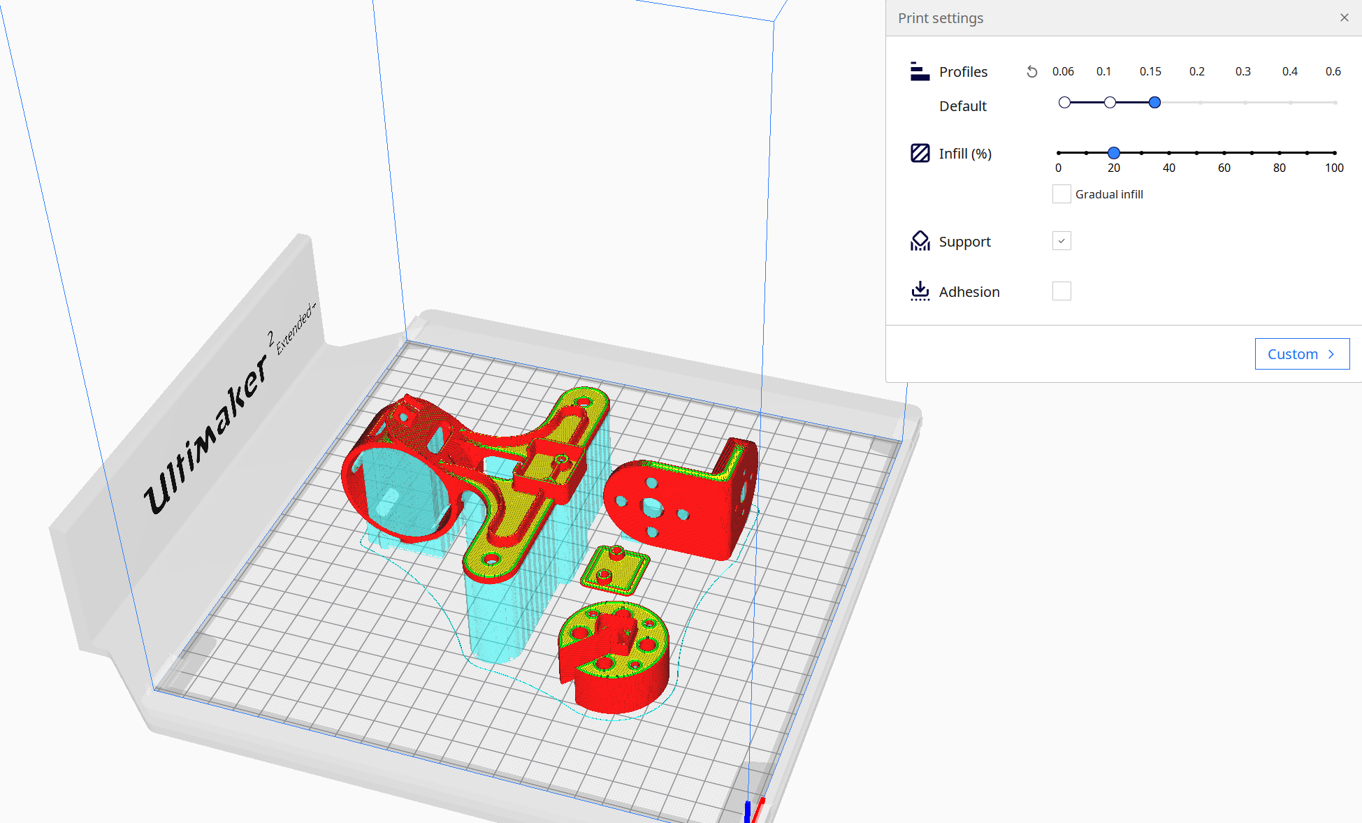
3D Printing support recommendations
There are four 3D-printed plastic components to be be produced.
- Camera Bracket
I recommend to print it face down, with break-away support material as shown in the photo. This way, you have the main loops of the perimeter printed in a very strong fashion. Yes, it’s a lot of support material and it can be annoying to remove from inside of the motor region.
- Head Base
Be sure to print this with the flat side oriented to the build plate. It has internal 3mm threads, which are quite strong, but which will only work well printed along the Z-axis. I found that in PLA or Tough PLA, the threads can last for 2-3 cycles, which is enough, given how convenient they are to work with!
- Middle Bracket
Print it so that you have the main “L-shape” on the build plate. This means that the plastic perimeter loops (which give strength to your FDM prints) are going to go across the main axes of the part.
- PCB Cover
No special considerations here.