This page will cover the 3D-printing and assembly of the GoodDog Bumble v0.2 robot.
Preparing the parts for printing
You will need to print 1 copy of each of the parts listed on this page: GitHub Link
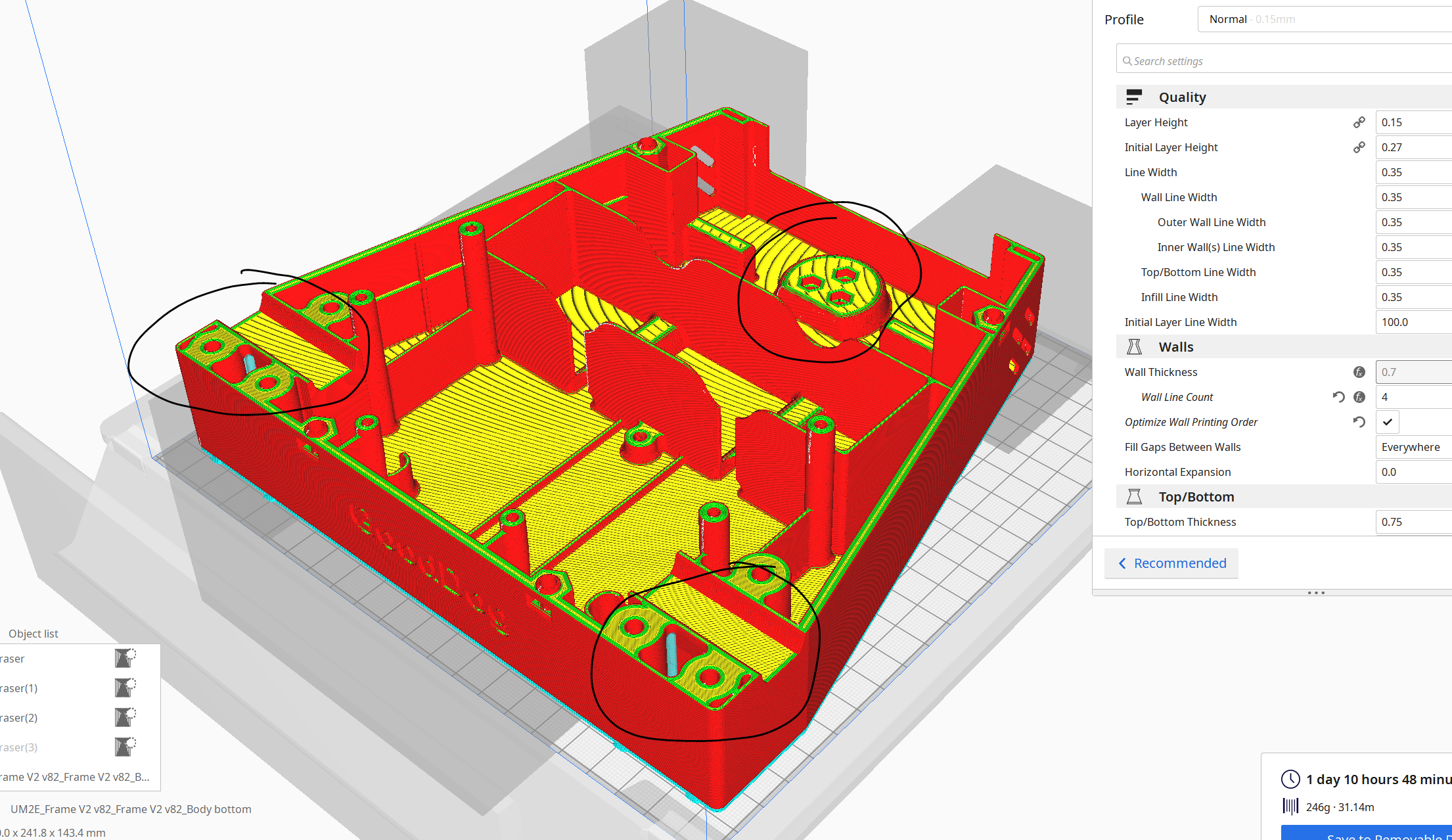
That’s a total of 9 parts, two of which are the gigantic case top and bottom case pieces. I have printed everything on an Ultimaker 2+ using Yellow Tough PLA.
Any printer with a 20x20cm build plate should work just as well, but you should expect around 60 hours of total print time and ~500g of material necessary.
Slicing settings needed:
- 20% gyroid infill
- 4 walls
- Supports are needed on some parts, but it’s doable with standard supports on a single extrusion printer.
Note: If you are using Ultimaker Cura as your slicer, then you can use the same settings we used with the files here.
Body Bottom
Body Top

Body Caster Wheel + Motor Mount

Head
Fasteners
Here are the required fasteners to assemble the robot. I recommend to get a generic M3 and M4 hex cap kit so that you have a bunch of sizes to choose from and make adjustments and hacks as necessary.
| # | Type | Size | Q-TY | Comment |
|---|---|---|---|---|
| 1 | Button Head Hex Drive Screw | M2.5 x 5 | 2 | Microphone mount |
| 2 | Button Head Hex Drive Screw | M3 x 6 | 2 | BaseCam PCB mount |
| 3 | Button Head Hex Drive Screw | M3 x 8 | 2 | Camera PCB |
| 4 | Button Head Hex Drive Screw | M3 x 10 | 9 | ODrive mount (4), Terminal mount (2), Head connection (3) |
| 5 | Button Head Hex Drive Screw | M3 x 16 | Charging plug mount | |
| 6 | Button Head Hex Drive Screw | M3 x 25 | 3 | Pololu wheel mount |
| 7 | Button Head Hex Drive Screw | M4 x 8 | 2 | Camera mount |
| 8 | ||||
| 9 | Socket Head Screw | M2.5 x 5 | 16 | Motors mount |
| 10 | Socket Head Screw | M4 x 8 | 2 | Power supply mount |
| 11 | Socket Head Screw | M4 x 16 | 4 | Casae connection |
| 12 | Socket Head Screw | M4 x 40 | 6 | Wheels clamps |
| 13 | Hex Nut | M3 | 4 | Pololu wheel mount (3), Charging plug mount (1) |
| 14 | Hex Nut | M4 | 10 | Wheels clamps (6), Case connection (4) |
| 15 | Zip ties short for rires | 16 | Head clip (2), Body clip (14) | |
| 16 | Zip ties long | 300mm | 2 | Battery mount |
Bottom Plate Assembly
Once you have printed all the parts, you can start assembly.
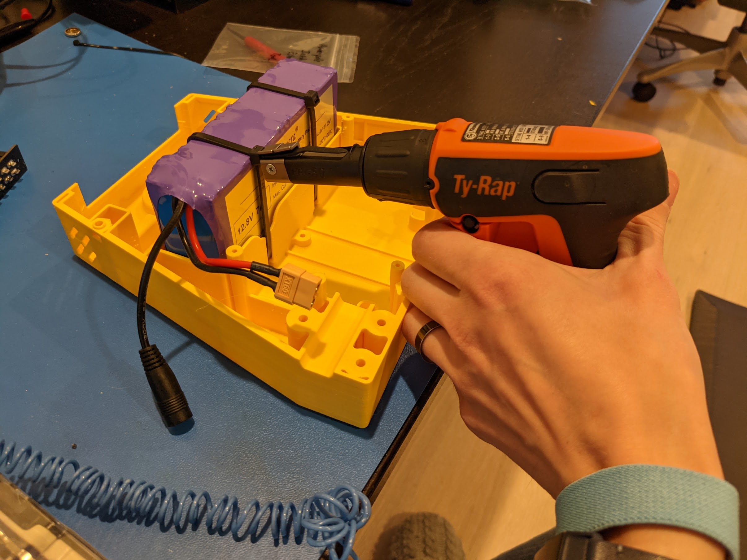
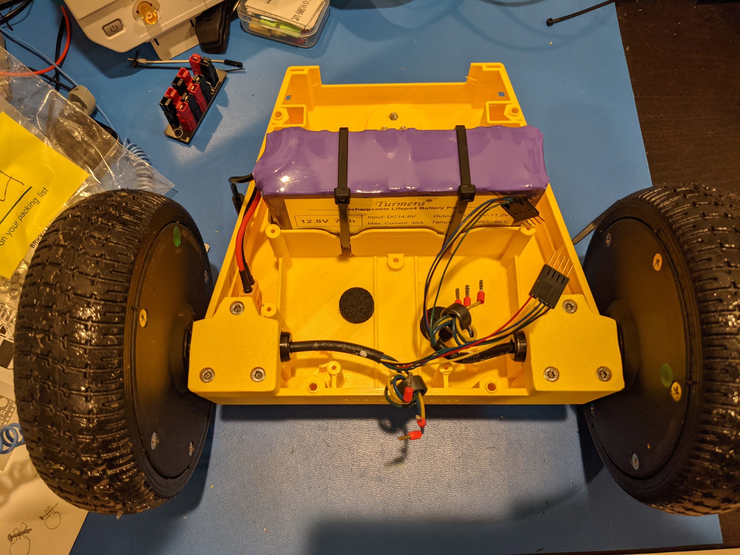
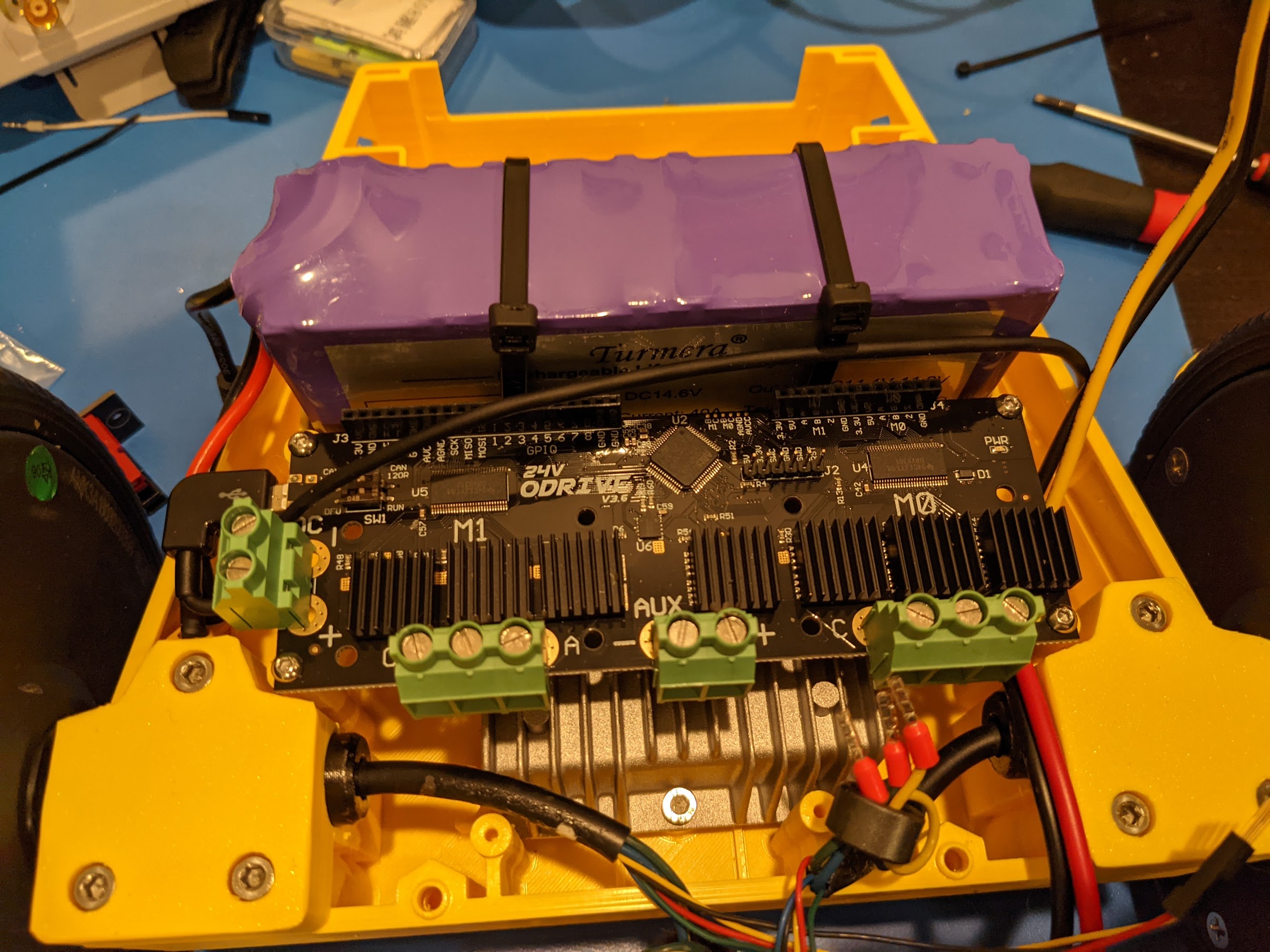
Install the battery. Use two big zip ties through the integrated clips to keep it tied down. I used a zip-tie gun set to around 40 pounds of pressure, but just make it firm without deforming the battery itself.
Install the Pololu caster wheel. Take the “Caster wheel base” 3D printed part, and the plastic base of the caster wheel and attach it to the matching hole at the bottom of the plate. Use M3x25 button head hex screws (a full socket cap will probably be too big), and some matching hex nuts. Once you attach the plastic base, put in the rollers into the caster wheel base, and snap in the retaining clip.
Attach the motors to the motor mounts. You’ll want the flat part of the hoverboard motor shaft to go against the bottom of the plate. Screw everything in with M4x40 hex cap screws, and M4 hex nuts that go into the traps at the bottom. (Be sure to clear out all of the support material from the nut traps)
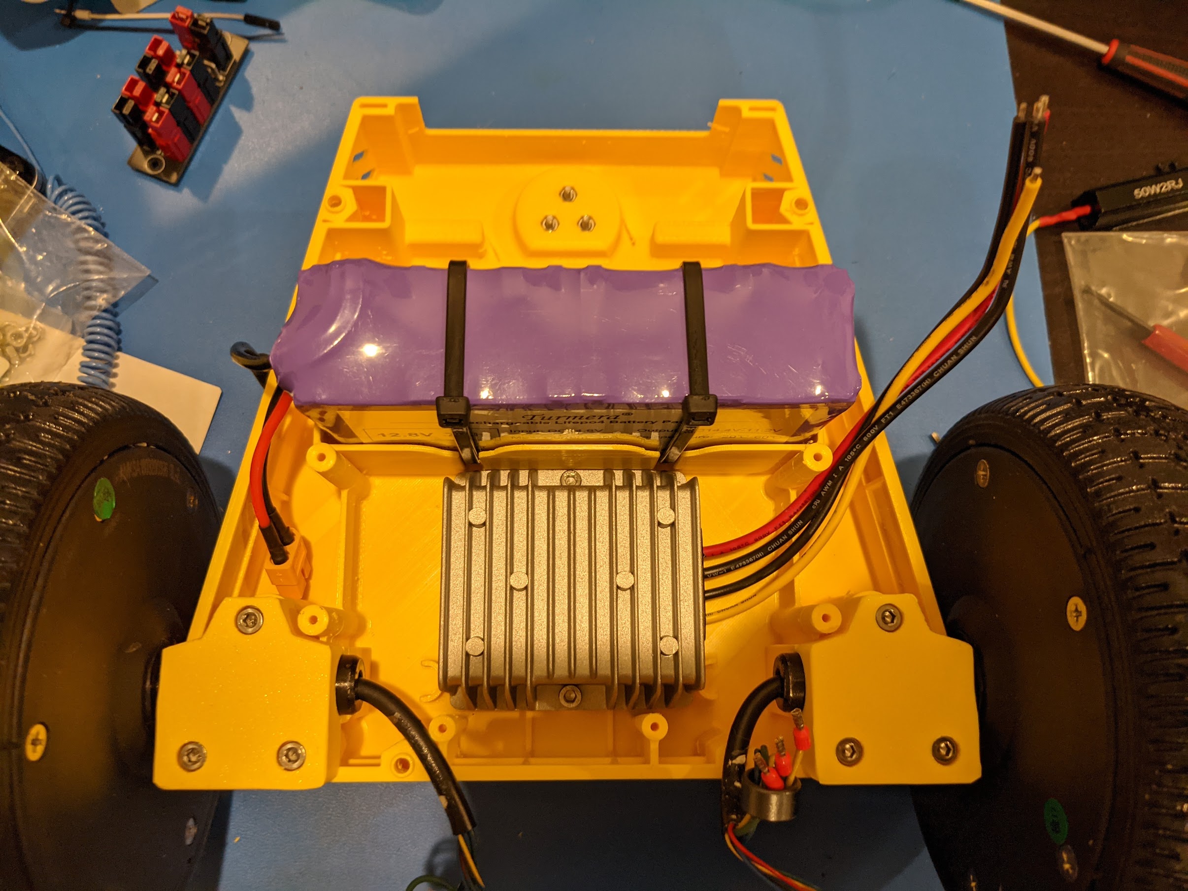
Install the DC-DC converter. This component is not strictly necessary, because the Jetson Xavier board runs on 12-20V input, and our battery is around 14V. However, I’ve noticed that there can be power spikes at a high enough level to be dangerous to the Jetson Xavier, so running it through a DC-DC converter is the safest option.
Prepare your ODrive 24V edition by soldering decoupling
capacitors to the motor hall effect sensor terminals. We used 22nf capacitors and followed the instructions here.
Don’t skip this step, if you do, the motor control will appear to work, but randomly after a few minutes of operation,
you will see the ERROR_ILLEGAL_HALL_STATE condition.
Mount the ODrive to the mounting posts at the front of the robot. I use M3x10 button head screws, they work perfectly for this application.
You can use this USB C to Micro-B cable which has the perfect length and connectors for this size of robot.
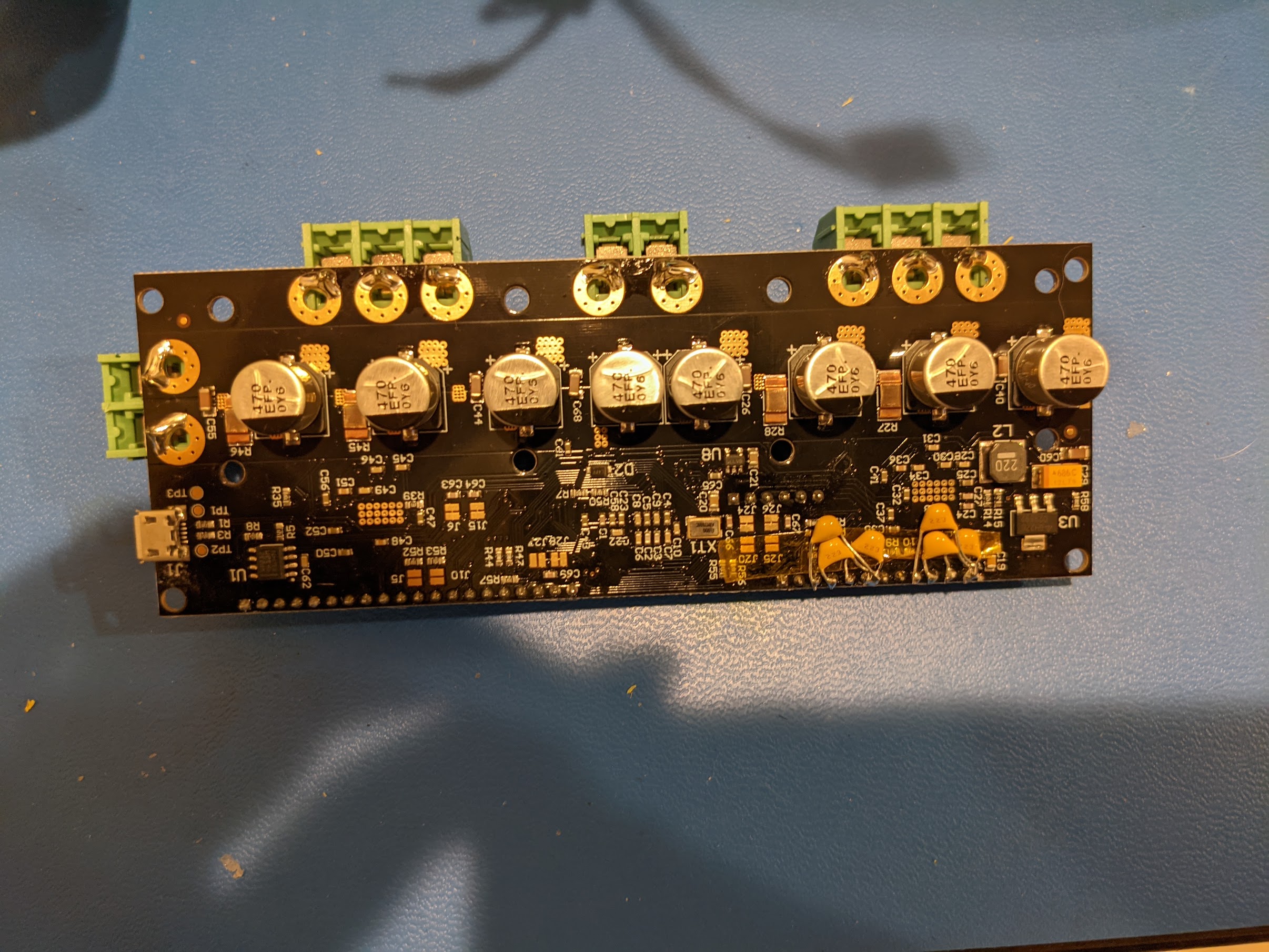
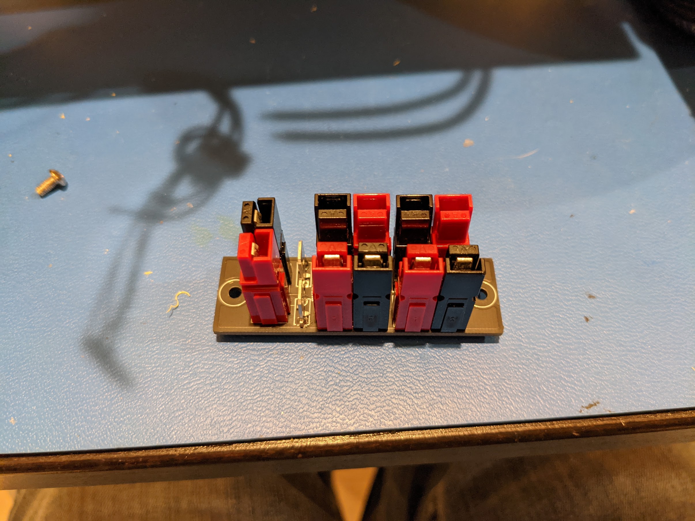
Build the Terminal Block
The handiest way to attach relatively high current wiring in a safe and easy manner is with “Anderson PowerPole” brand connectors. You can get this board built and shipped with jlcpcb.com for around $15, and it’s very handy for future projects.
Instructions:
- Download the Gerber Files
- Go to jlcpcb.com and order it. You should expect to pay around $2, plus $10 shipping. No special PCB characteristics are required.
- Assemble the board, you’ll need 10x PCB Anderson Connectors, and 2x connector tabs
- You can get an inexpensive Power Pole crimper and a couple connectors from PowerWerx.
Attach the Terminal Block
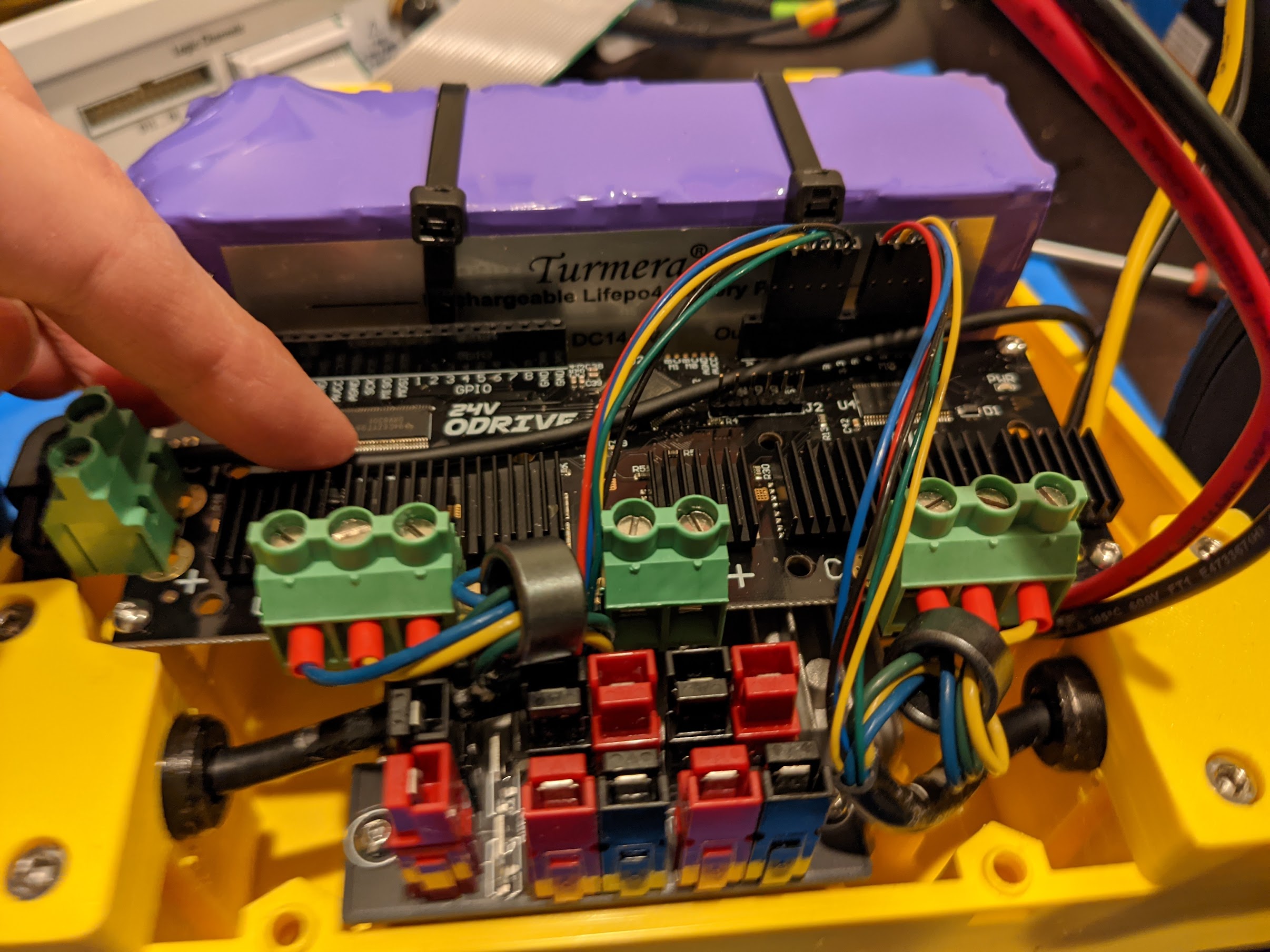
Wire your Motors and ODrive
Shorten up the 3 big power wires from your motors as much as you think is prudent, and attach some wire ferrules to the end. Ferrules are important, because they will effectively turn the multi-strand wire in the motor wires back to single strand which is very easy to screw into the terminal blocks on the ODrive. It will also help prevent a single strand of wire getting loose and causing a short-circuit.
I used this wire ferrule crimper which was very cheap on Amazon and probably include more crimps than most mortal humans will ever use.
I also added some ferrite cores to the motor wires, before attaching them to the ODrive board. This helps reduce EMI.
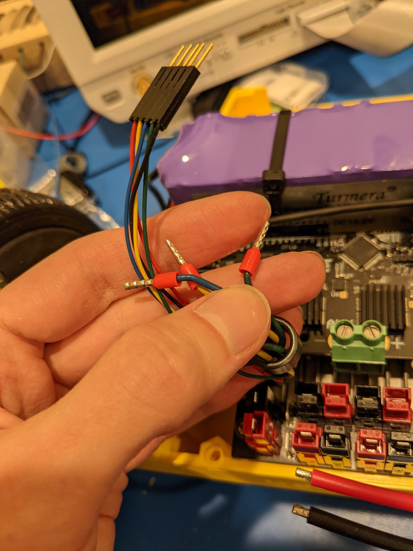
The other 5-stranded wires are used to send the hall effect encoder signal from the motor to the ODrive controller. This lets you run the motor efficiently at very low speeds, and also have some understanding of how many turns of the wheel have been made for odometry.
My favorite solution here is to use Molex SL connectors. They are size-compatible with what are known as “Dupont connectors” (those 0.1inch pitch connectors that you use to assemble Arduino circuits, etc). However, they are more reliable, and you can more easily find proper crimpers.
Check out this guide on proper crimping and some additional explanation of crimp connections.
Build around an 8 inch cable to connect the ODrive (wire ferrules to go into the green block labelled + and -) and the terminal block which distributes power.
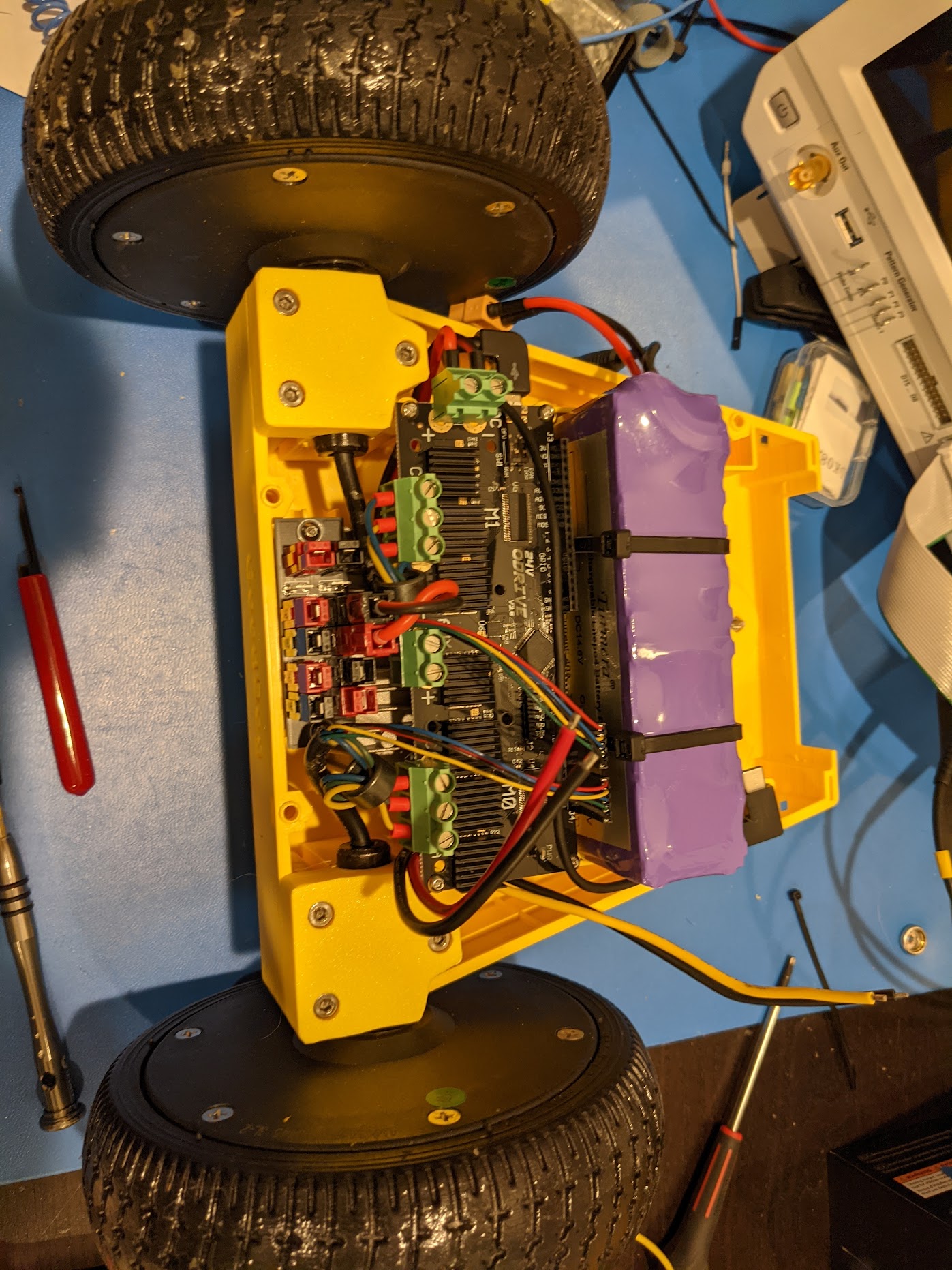
Quick checkup, at this point you should have the following things done
- 14V LiFePO4 battery installed
- Hoverboard motors mounted
- Caster wheel mounted
- DC-to-DC Converter installed, wiring not yet created
- ODrive 24V edition mounted
- Power distribution board soldered up, and mounted
- Power connected to the ODrive as shown
- Each of the motor power leads connected to the ODrive
- Each of the motor encoders connected to the ODrive
Finish wiring the bottom case assembly
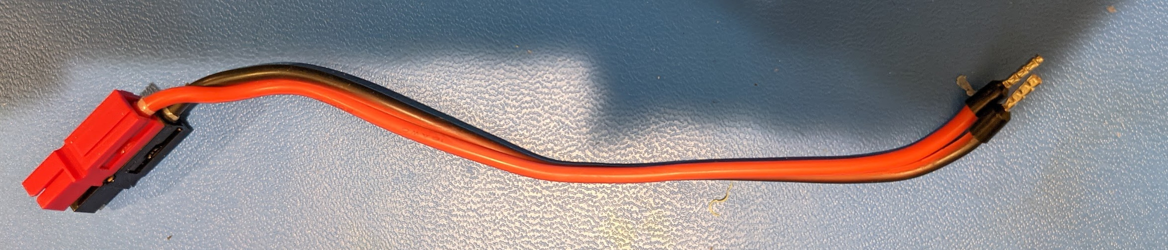
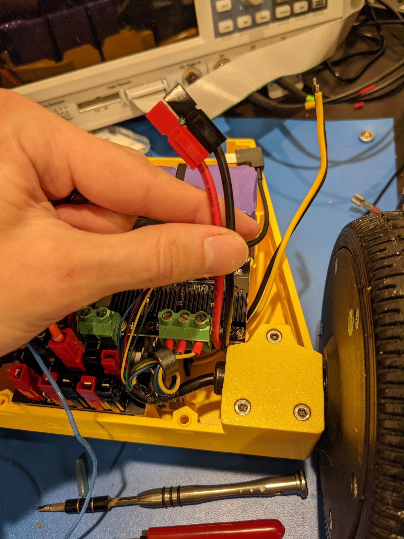
Next, using 14 or 16 AWG wire, make a cable that will connect the battery to the power distribution board.
I used these XT60 Pigtails from Amazon, and the crimped 30Amp Anderson PowerPole connectors to the other side as shown.
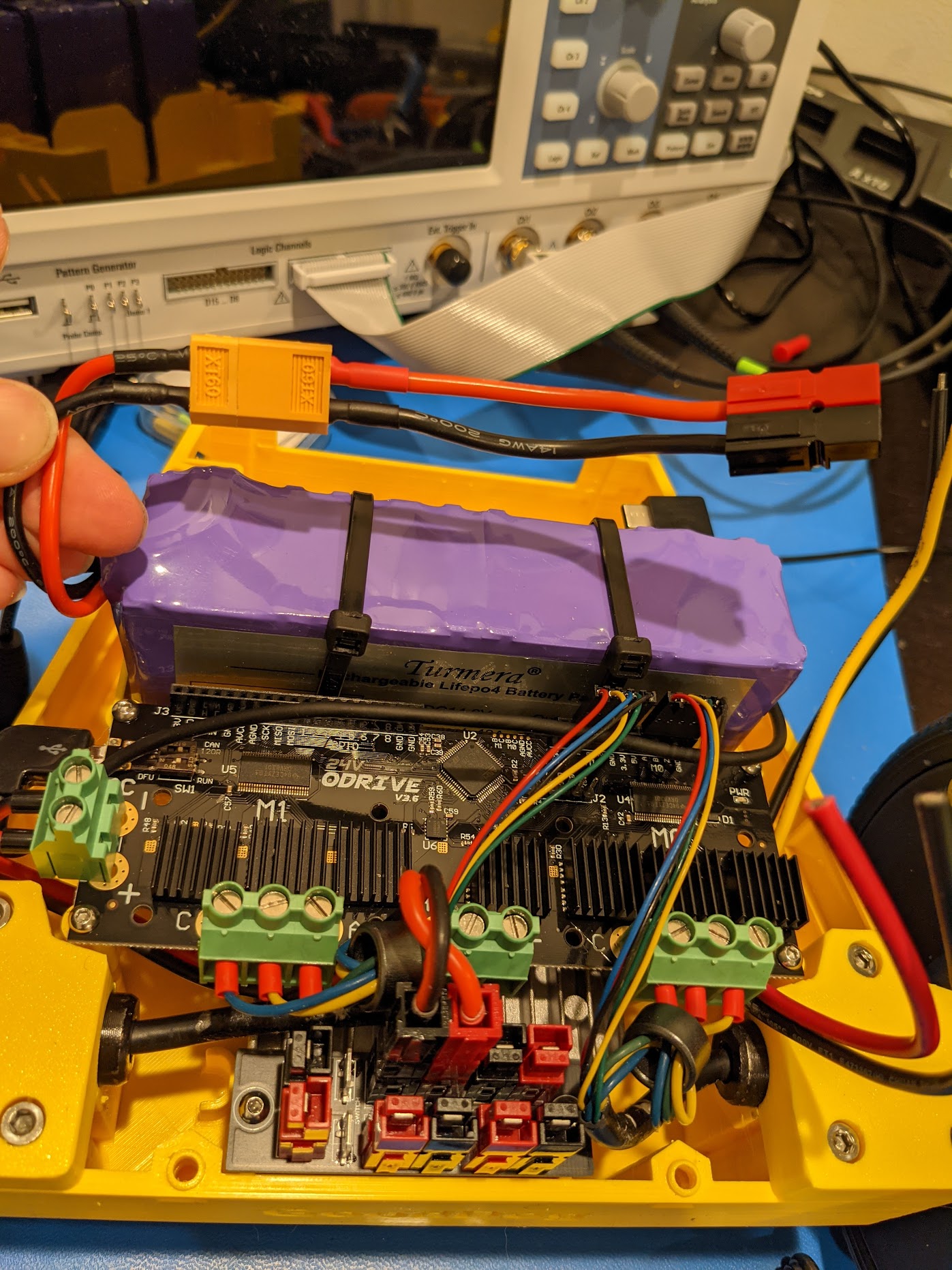
Take the Red and Black leads off of the DC-to-DC converter, and crimp on some 30 Amp Anderson PowerPole connectors to them.
Plug that into the power distribution board.
Take the Yellow and Black leads from the DC-to-DC converter, these are going to go into the Jetson Xavier AGX board. This board takes a 2.5mm ID, 5.5mm OD Plug, which may be a bit bigger than the 2.1x5.5mm plugs which are most common in electronics projects.
The best way I found to accomplish this was using this cable assembly from Digi-key, which already has a right-angle connector on it.
The easiest way to attach these two wires is with some heat shrinking “butt splice” connectors.
I like these official Molex Perma Seal ones, which are also available very cheaply from Waytek Wire with matching crimpers.
You can get some clones of these Perma Seal products on Amazon, for a bit less money. However, I have found that they are somewhat unreliable. If you do the crimp, and it works (you tug on the wires and they don’t come apart), then you are fine. But maybe 30% of the time, something will go wrong in the crimping process, and you’ll have to restrip the wire and try again. The Molex brand ones, with official crimp tool, work 100% of the time for me.
Be sure to add a ferrite core to the end of the wire where it will attach to the Jetson Dev Kit.
At this point, you are done with the bottom part of the case!
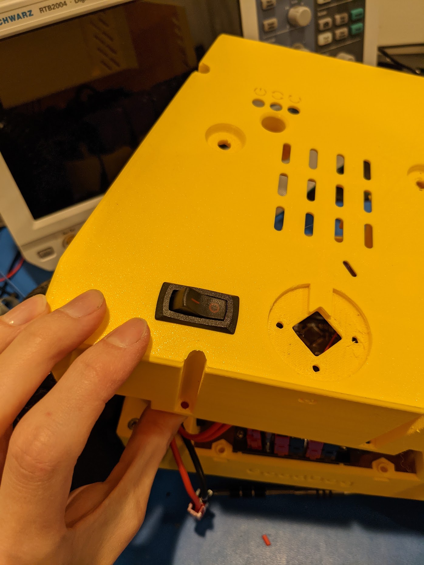
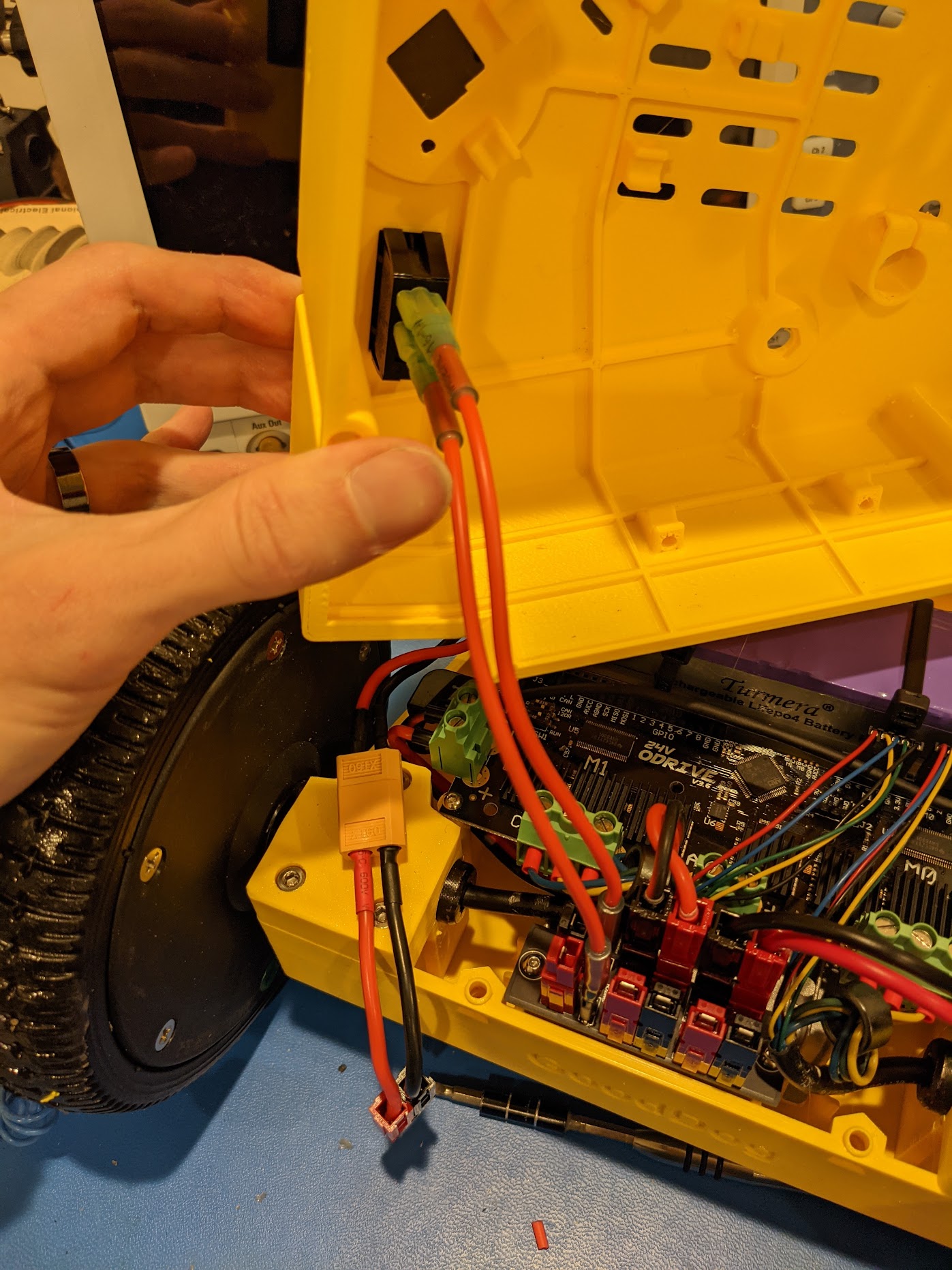
Assembling the power switch
We’ve gotten ourselves a nice little rocker power switch so now it’s time to attach it.
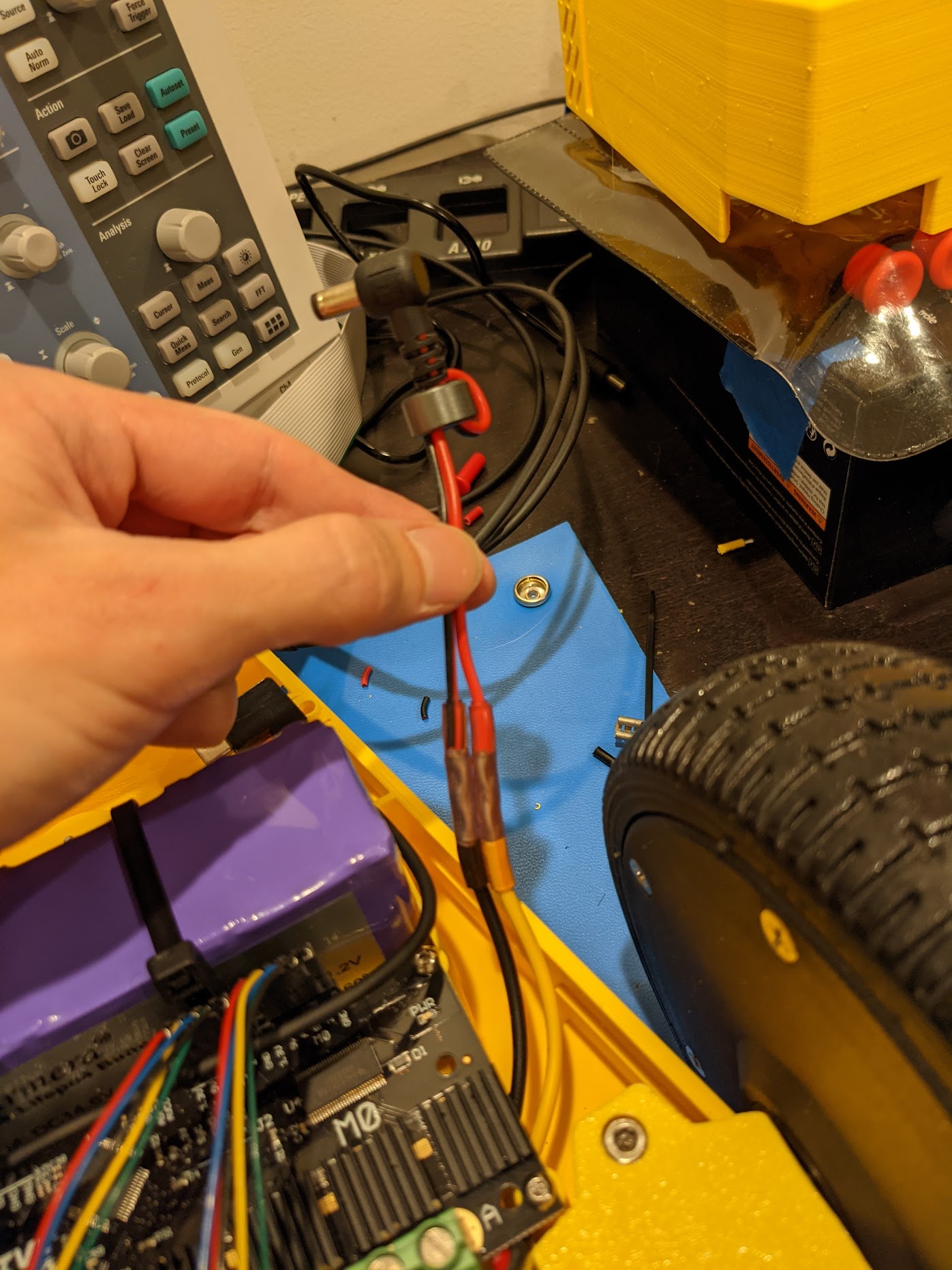
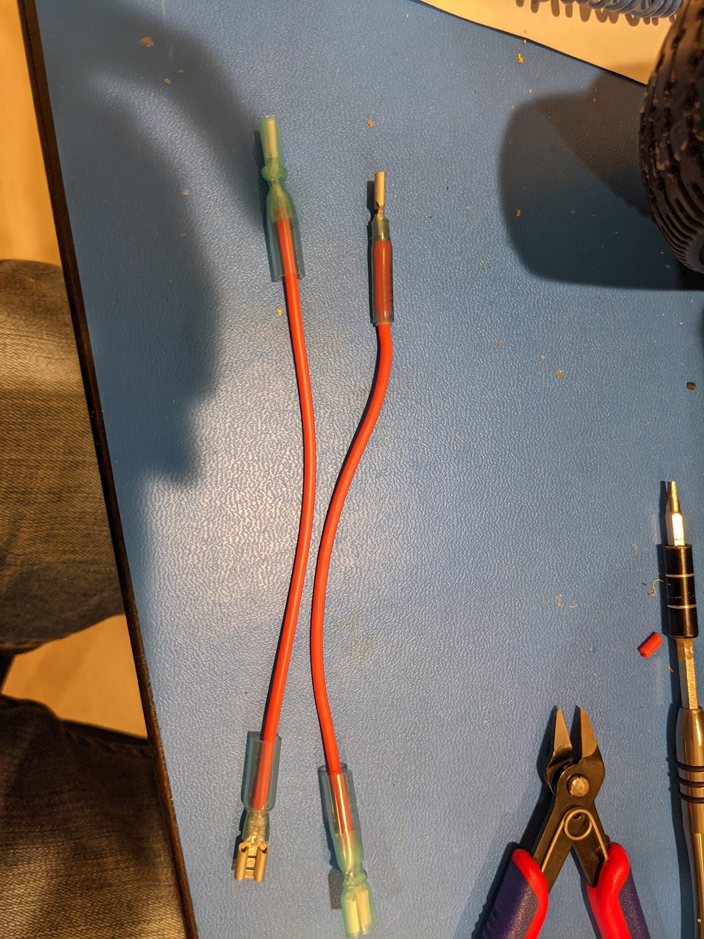
Build yourself two power leads that will go between the switch and the power distribution board. You want around 8 inches or so, to give yourself room to open the case later, without being excessively long to introduce EMI.
Most power switches that you find are going to be using so called “quick connect” 0.25inch spade connectors. It’s a pretty standard part that you’ll see on a lot of electronics, and it can handle 30 amps or so pretty reliably, plenty for our application.
I went all out with these insulated, heat shrinking, spade connectors. You can find cheaper ones, basically any 0.25inch “quick disconnect” spade crimp terminals will work.
If that looks good, then you should be able to plug in your battery, the switch leads, and hit the power switch! You should see a green light on the ODrive board at this point.
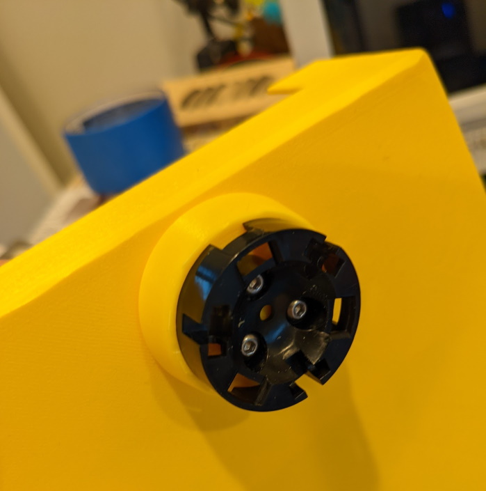
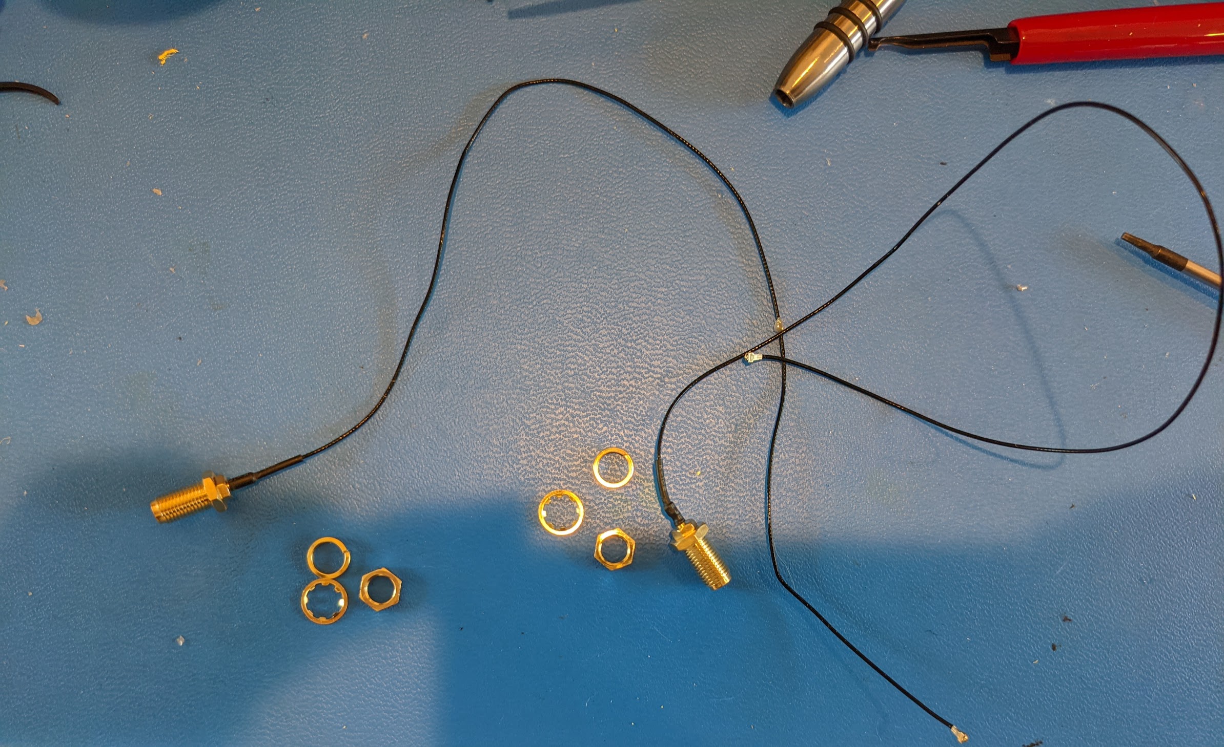
Installing the Wifi / Bluetooth antennas
On the bottom of your Jetson board, attach a PCI-E Wifi module. I recommend to use an Intel 8265, which is very well tested and works well with the Jetson ecosystem. It’s going to use a really tiny “U.FL IPX4” connector, and the robot body will have two antennas, one for the Wifi and one for the Bluetooth.
The antenna connectors that I used came with a hex nut, a lock nut, and a spring washer. Be sure to use all three of these on the top part of the case, so that your connections don’t get loose over time.
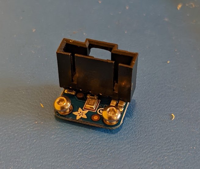
Installing the Microphone
Take your Adafruit SPH0645LM4H breakout board, and solder on a connector as in the picture. You’ll then use some M2.5x5 screws to attach the microphone to the case. Be sure that the port of the microphone is pointing outwards.
I used a Molex SL 6 pin header so that you can have a nice clear connection with polarity between this board and the Jetson Xavier.
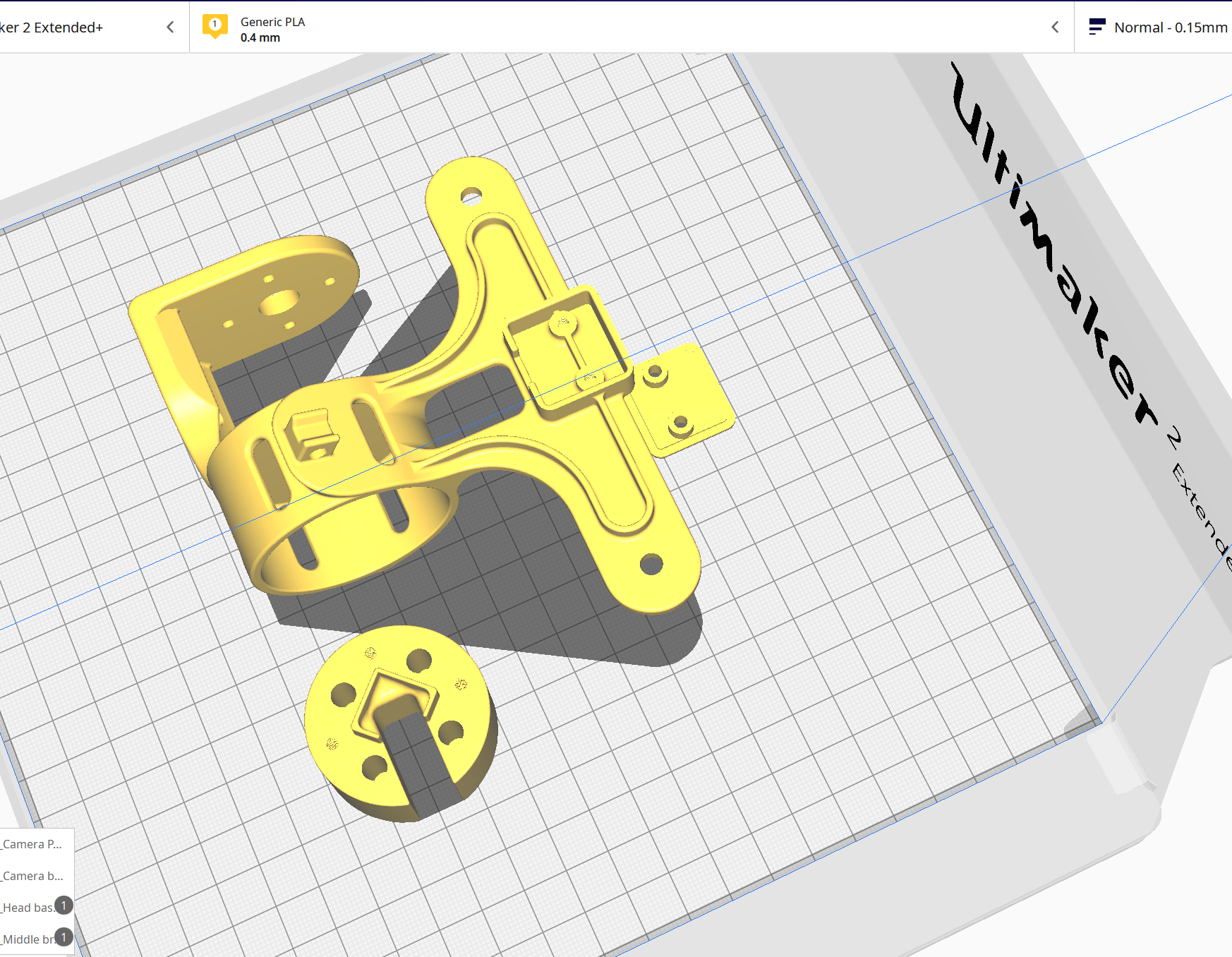
Install the Gimbal Head
- Follow the Gimbal Electronics instructions to install and wire up the gimbal camera head.
Wire up Xavier Expansion Port
You’ll need to connect two devices to the 40-pin expansion port on the Jetson Xavier.
- UART RX/TX for the SimpleBGC
- I2S Microphone SPH0645LM4H breakout board
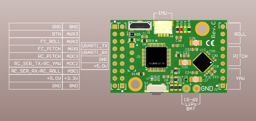
| Connector Pin # | Connector Label | Device Connection |
|---|---|---|
| 1 | 3V3 | SEL on Microphone 2 |
| 2 | 5V0 | |
| 3 | SDA1 | |
| 4 | 5V0 | |
| 5 | SCL1 | |
| 6 | GND | |
| 7 | GPIO_GCLK | |
| 8 | TXD0 | USART1_RX on SimpleBGC |
| 9 | GND | GND on SimpleBGC |
| 10 | RXD0 | USART1_TX on SimpleBGC |
| 11 | GPIO_GEN0 | |
| 12 | GPIO_GEN1 | BCLK on Microphone |
| 13 | GPIO_GEN2 | |
| 14 | GND | |
| 15 | GPIO_GEN3 | |
| 16 | GPIO_GEN4 | |
| 17 | 3V3 | 3V on Microphone |
| 18 | GPIO_GEN5 | |
| 19 | SPI_MOSI | |
| 20 | GND | GND on Microphone |
| 21 | SPIO_MISO | |
| 22 | GPIO_GEN6 | |
| 23 | SPI_SCLK | |
| 24 | SPI_CE0_N | |
| 25 | GND | |
| 26 | SPI_CE1_N | |
| 27 | ID_SD | |
| 28 | ID_SC | |
| 29 | GPIO5 | |
| 30 | GND | |
| 31 | GPIO6 | |
| 32 | GPIO12 | |
| 33 | GPIO13 | |
| 34 | GND | |
| 35 | GPIO19 | LRCL on Microphone |
| 36 | GPIO16 | |
| 37 | GPIO26 | |
| 38 | GPIO20 | DOUT on Microphone |
| 39 | GND | SEL on Microphone 1 |
| 40 | GPIO21 |
I made the connections with a set of Molex SL crimpers as before.
There are some great resources on the Jetson Hacks website, including more information and diagrams on the 40-pin connections. Jetson Hacks 40 pin header docs
Remember, that once you make the connections, you’ll still need to provision everything.
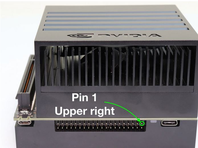
Install the Jetson Xavier
The actual Jetson Xavier dev kit should slot in nicely at the back of the robot. Plug in the power connection, the 40-pin header connections, the wifi antennas, the camera USB, and the USB connection to the ODrive.
One last thing: install a nice big micro SD card to store the ROS bag files which the robot will record while it’s operating.
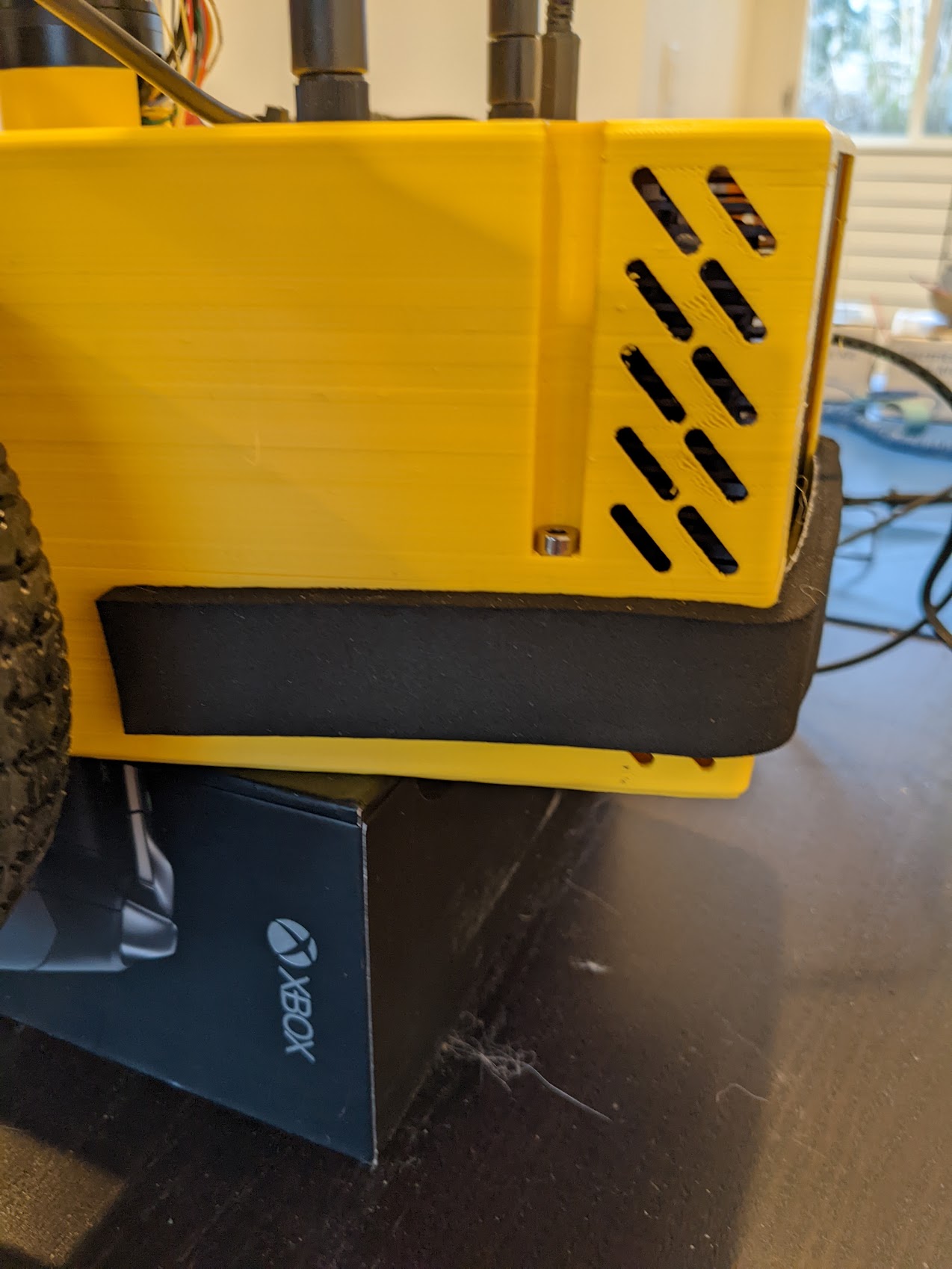
Seal up the case and install bumpers
Once everything is ready and tested, you can use 4 M4x40 hex nuts to seal up the case. There is a spot for a trapped nut on the bottom of the case, and the nuts come in from the top.
Make sure that your wiring is tight and secure, and that there are no bulges sticking out through the case. It should really be a snug easy fit, but it can be finnicky if your wiring is too large or rats-nesty.
I used some of this Neoprene foam stripping around the case to give the robot some padding in case it bumps into anything. As an added benefit, it keeps the trapped nuts in place, so you don’t have to worry about them falling out if you ever need to open the case.