Once you get your NVIDIA Jetson AGX Dev Kit, you will need to setup the SDK Manager on a compatible computer, and then flash your Dev Kit with the latest L4T (Linux for Tegra) images. Sadly, NVIDIA is often really slow releasing support for new operating systems, so as of August 2022, you would need an Ubuntu 20.04 image to do the flashing and use the tools.
Thankfully, they have a docker image that you can use for flashing. Instructions based on these: https://docs.nvidia.com/sdk-manager/docker-containers/index.html
-
Download the image from https://developer.nvidia.com/nvidia-sdk-manager-docker-image (As of August August 2022, we are using SDK Manager version 1.8.1, and Jetson 5.0.2: sdkmanager-1.8.1.10392)
-
From a terminal, load the Docker image:
docker load -i ./sdkmanager_[version].[build#]_docker.tar.gz
- Tag the image as latest, for more convenience
docker tag sdkmanager:[version].[build#] sdkmanager:latest
-
Run the sdk manager in CLI mode to confirm that it works, and query the available installation types
docker run -it --rm sdkmanager --query -
Connect the provided power cable to your Jetson Xavier board, and connect the USB C port that’s next to the three power buttons to your computer. Then, boot the Jetson into Recovery mode by pressing and holding the inner most “recovery” button, while pressing the outer power button.
-
If that checks out, then you want the latest
JETSON_AGX_XAVIER_TARGETSas follows:docker run -it --privileged -v /dev/bus/usb:/dev/bus/usb/ --network host -it --rm sdkmanager --cli install --logintype devzone --staylogin --product Jetson --version 5.0.2 --targetos Linux --target JETSON_AGX_XAVIER_TARGETS --flash all
- Note, you can also flash it on Windows, using WSL. I used an Ubuntu 20.04 WSL instance, and followed these instructions
- https://devblogs.microsoft.com/commandline/connecting-usb-devices-to-wsl/ to install it. You may need to run the
usbipd wsl attach --busid x-ycommand 2-3 times, and do it rapidly when the devices disconnects during the flashing process. Finally, in this case you may need to use the hardware Ethernet port to finalize the installation.
-
This will flash the OS image, and then wait for you to run the
oem-configprocess. You can either run this by plugging in a keyboard and monitor, or by connecting to the exposed serial port:screen /dev/ttyACM0 -
Once that’s done, return to the sdkmanager window, and continue the setup.
-
You should be able to SSH to your device:
ssh robot@192.168.55.1 -
Once you SSH in, you should do one last
apt-get update && apt-get upgrade, and then disable a few services that should not be necessary (like the GUI and docker)
# Disable gnome/GUI login
sudo systemctl set-default multi-user.target

# Disable docker
sudo systemctl disable docker.service
sudo systemctl disable docker.socket
sudo systemctl disable containerd

# Disable some other random crap you don't need
sudo systemctl disable whoopsie
-
You can also set things up for the 4 core 30W power mode, which should be more than sufficient for fast operation.
sudo nvpmodel -m 5 -
And finally, set up a wifi connection (you’ll need an M.2 Wifi module, I recommend an Intel 8265, plus an externally connected antenna.)
sudo nmcli -a d wifi connect [wifi_sssd]
NB: If your host computer is Ubuntu, you may experience some frequent connections and disconnections via the USB-Ethernet interface. To fix that, I recommend disabling the “connect automatically” feature for those Jetson connections within the provided Network Manager.
How to set up connection to the Simple BGC controller
There are a few steps needed to get the Simple BGC controller to be able to talk back to the Jetson Xavier via the integrated UART.
# Disable the nvgetty service, which by default takes over the UART on the 40 pin connector
sudo systemctl disable nvgetty.service

# Add the default "robot" user to the tty and dialout groups on linux
sudo usermod -a -G tty robot
sudo usermod -a -G dialout robot

# Set a UDev rule so that the /dev/ttyTHS0 port is accessible to the proper group
sudo -s
echo 'SUBSYSTEM=="tty", GROUP="tty", MODE="0660"' > /etc/udev/rules.d/99-user-tty.rules
How to set up and format a Micro SD Card
It helps to have a huge 128GB or bigger MicroSD card to store the recordings of your robot’s experiences. You’ll want one with “C10, U3, V30, A2” or similar specs, with a good consistent writing rate.
Note, we are using a FAT32 filesystem here, which may bog down at some point, you should keep an eye on your bag files to see if they have gaps in their recorded events.
Also note, there is a bug with the Xavier platform, if you have an ext4 partitioned SD card inserted at boot, the bootloader will attempt to use it, leading to weird issues (like the device tree overlay for the microphone not loading).
# Format the card as ext4 for good performance on linux
sudo lsblk # Find your card device name, usually it's /dev/mmcblk1p1
sudo mkfs.vfat -F32 /dev/mmcblk1p1 # Format as fat32

sudo nano /etc/fstab

# Add the following line at the bottom
/dev/mmcblk1p1       /media/card           vfat           rw,uid=robot,gid=robot,nofail,noatime              0 0

# Make a place to mount it in /media/card
sudo mkdir /media/card
sudo chown robot /media/card
sudo chgrp robot /media/card

# Check that your fstab worked
sudo mount -a
How to set up the ODrive motor controller
- First, connect the battery to the DC power input, plus the AUX pin to the included resistor, the motors, and then the motor hall effect sensors on the ODrive. The hall effect sensors from most hoverboard motors are going to have the following connections:
| Wire Color | Pin |
|---|---|
| Red | 5V |
| Yellow | A |
| Blue | B |
| Green | Z |
| Black | GND |
-
The next step is to calibrate the motors, and it’s easiest to just temporarily connect a USB cable between the Jetson and the ODrive board for this step. Later, we will set up the CANBUS for reliable communications.
-
Install the ODrivetool as per these instructions: https://docs.odriverobotics.com/#downloading-and-installing-tools
# I had to adjust the commands as follows to install on the Jetson Xavier
pip3 install Cython
sudo pip3 install --upgrade odrive matplotlib==3.2.2
Also, be sure to set up the proper udev rules, they won’t come in automatically on the Jetson.
echo 'SUBSYSTEM=="usb", ATTR{idVendor}=="1209", ATTR{idProduct}=="0d[0-9][0-9]", MODE="0666"' | sudo tee /etc/udev/rules.d/91-odrive.rules
sudo udevadm control --reload-rules
sudo udevadm trigger

# And add your user to the dialout group, assuming "robot" is your username
sudo adduser robot dialout
- Run the instructions below to configure both hoverboard motors. They are adapted from https://docs.odriverobotics.com/hoverboard
Note, if you run into a PHASE_RESISTANCE_OUT_OF_RANGE error, then you may need to increase the resistance_calib_max_voltage value.
# Configure Motor 0
odrv0.config.enable_brake_resistor = True
odrv0.axis0.motor.config.pole_pairs = 15

odrv0.axis0.motor.config.resistance_calib_max_voltage = 8 # Should be between 4-8 for most hoverboard motors
odrv0.axis0.motor.config.requested_current_range = 25 #Requires config save and reboot
odrv0.axis0.motor.config.current_control_bandwidth = 100
odrv0.axis0.motor.config.current_lim = 5
odrv0.axis0.motor.config.torque_constant = 8.27 / 16 # Replace 16 with KV if you know it

odrv0.axis0.encoder.config.mode = ENCODER_MODE_HALL
odrv0.axis0.encoder.config.cpr = 90
odrv0.axis0.encoder.config.calib_scan_distance = 150
odrv0.config.gpio9_mode = GPIO_MODE_DIGITAL
odrv0.config.gpio10_mode = GPIO_MODE_DIGITAL
odrv0.config.gpio11_mode = GPIO_MODE_DIGITAL

odrv0.axis0.encoder.config.bandwidth = 100
odrv0.axis0.controller.config.pos_gain = 1
odrv0.axis0.controller.config.vel_gain = 0.02 * odrv0.axis0.motor.config.torque_constant * odrv0.axis0.encoder.config.cpr
odrv0.axis0.controller.config.vel_integrator_gain = 0.1 * odrv0.axis0.motor.config.torque_constant * odrv0.axis0.encoder.config.cpr
odrv0.axis0.controller.config.vel_limit = 2
odrv0.axis0.controller.config.vel_limit_tolerance = 2
odrv0.axis0.controller.config.control_mode = CONTROL_MODE_VELOCITY_CONTROL

odrv0.save_configuration()
odrv0.reboot()

# Now, calibrate the motor, then the hall effect sensors for that motor
odrv0.axis0.requested_state = AXIS_STATE_MOTOR_CALIBRATION
odrv0.axis0.motor.config.pre_calibrated = True

odrv0.axis0.requested_state = AXIS_STATE_ENCODER_HALL_POLARITY_CALIBRATION
odrv0.axis0.requested_state = AXIS_STATE_ENCODER_OFFSET_CALIBRATION
odrv0.axis0.encoder.config.pre_calibrated = True

odrv0.save_configuration()
odrv0.reboot()

# Repeat the configuration for the second motor
odrv0.axis1.motor.config.pole_pairs = 15

odrv0.axis1.motor.config.resistance_calib_max_voltage = 8 # Should be between 4-8 for most hoverboard motors
odrv0.axis1.motor.config.requested_current_range = 25 #Requires config save and reboot
odrv0.axis1.motor.config.current_control_bandwidth = 100
odrv0.axis1.motor.config.current_lim = 5
odrv0.axis1.motor.config.torque_constant = 8.27 / 16 # Replace 16 with KV if you know it

odrv0.axis1.encoder.config.mode = ENCODER_MODE_HALL
odrv0.axis1.encoder.config.cpr = 90
odrv0.axis1.encoder.config.calib_scan_distance = 150
odrv0.config.gpio12_mode = GPIO_MODE_DIGITAL
odrv0.config.gpio13_mode = GPIO_MODE_DIGITAL
odrv0.config.gpio14_mode = GPIO_MODE_DIGITAL

odrv0.axis1.encoder.config.bandwidth = 100
odrv0.axis1.controller.config.pos_gain = 1
odrv0.axis1.controller.config.vel_gain = 0.02 * odrv0.axis1.motor.config.torque_constant * odrv0.axis1.encoder.config.cpr
odrv0.axis1.controller.config.vel_integrator_gain = 0.1 * odrv0.axis1.motor.config.torque_constant * odrv0.axis1.encoder.config.cpr
odrv0.axis1.controller.config.vel_limit = 2
odrv0.axis1.controller.config.vel_limit_tolerance = 2
odrv0.axis1.controller.config.control_mode = CONTROL_MODE_VELOCITY_CONTROL

odrv0.save_configuration()
odrv0.reboot()

# And repeat the calibration steps for the second motor
odrv0.axis1.requested_state = AXIS_STATE_MOTOR_CALIBRATION
odrv0.axis1.motor.config.pre_calibrated = True

odrv0.axis1.requested_state = AXIS_STATE_ENCODER_HALL_POLARITY_CALIBRATION
odrv0.axis1.requested_state = AXIS_STATE_ENCODER_OFFSET_CALIBRATION
odrv0.axis1.encoder.config.pre_calibrated = True

odrv0.save_configuration()
odrv0.reboot()
How to set up an I2S interface microphone with a Jetson Xavier.
If you purchase a https://www.adafruit.com/product/3421 microphone, then your robot will be able to listen to audio signals. Note that the “port” (where the sound comes in) to the microphone is on the bottom side of the PCB, so you’ll want to leave that up and exposed.
I recommend directly soldering some female-female jumper cables (https://www.adafruit.com/product/266) to the microphone breakout board, and then plug the connectors in the 40pin expansion header on the Jetson.
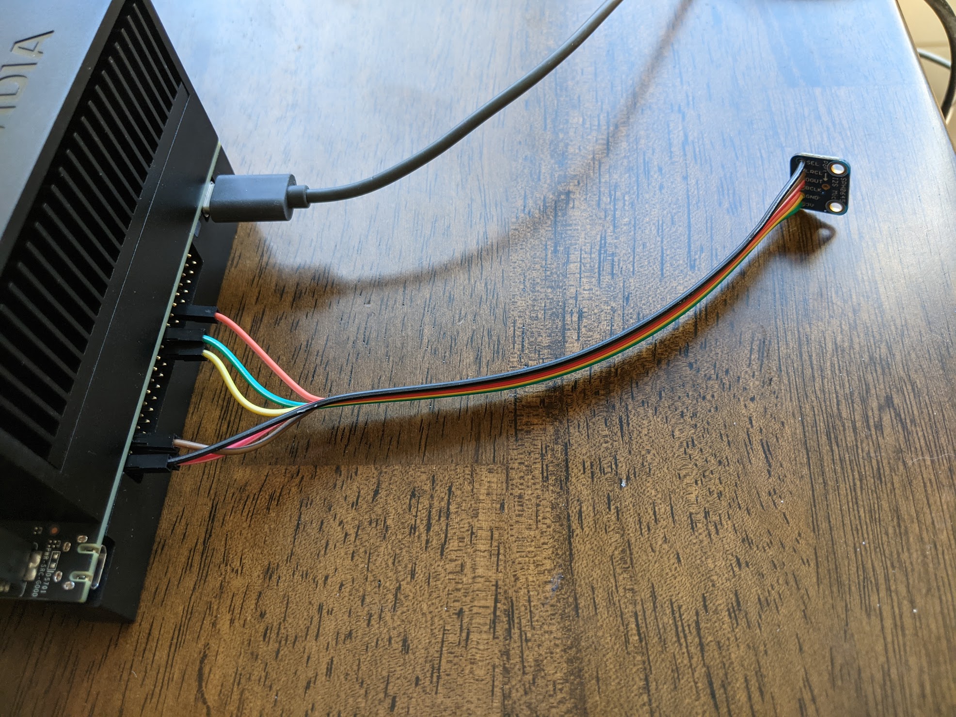
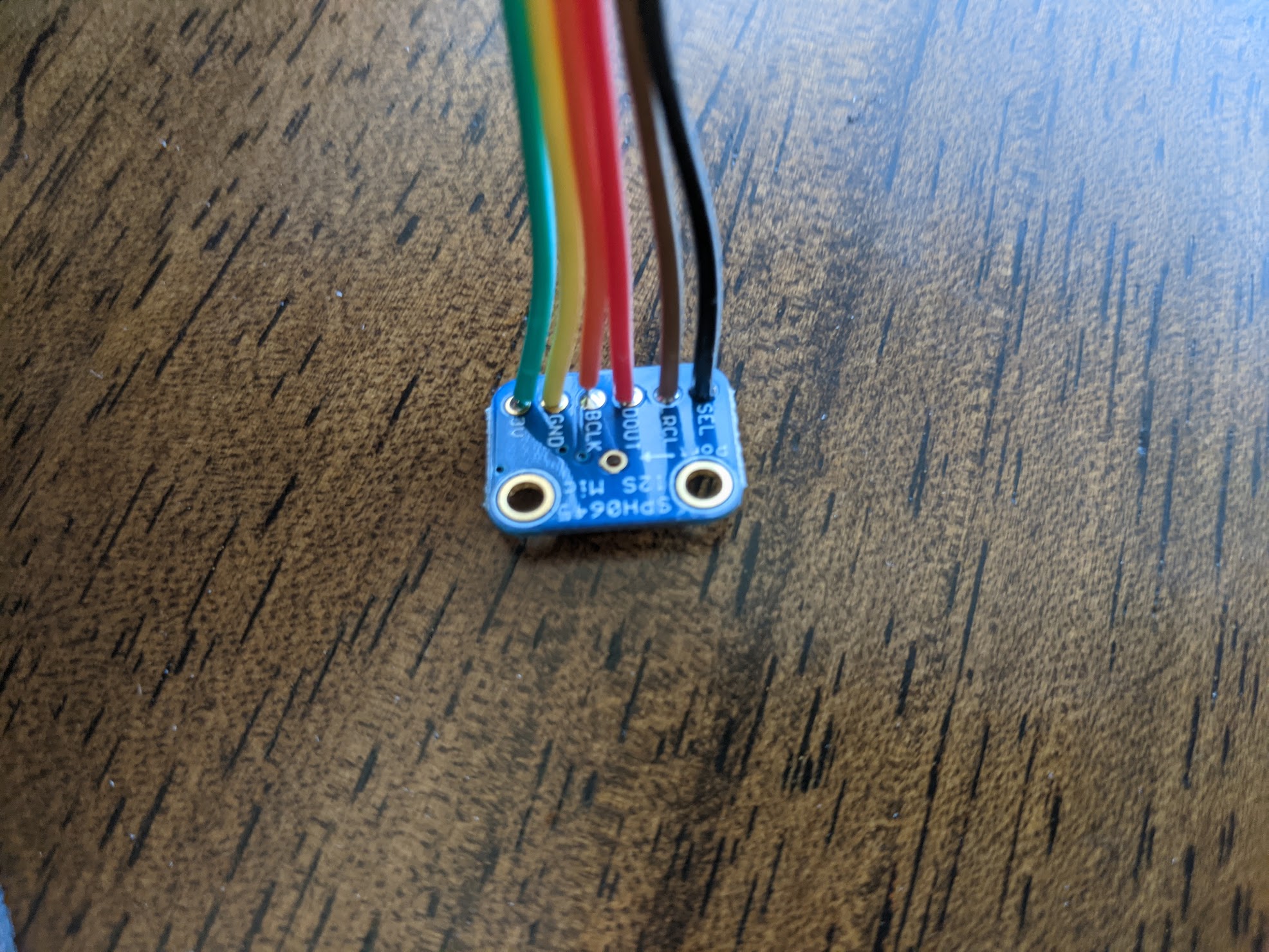
Connect according to the pinout below
| Jetson Xavier | Mic Breakout |
|---|---|
| Pin 17 (3.3V) | 3V |
| Pin 20 (GND) | GND |
| Pin 12 (I2S2_CLK) | BCLK |
| Pin 38 (I2S_SDIN) | DOUT |
| Pin 35 (I2S_FS) | LRCL |
| Pin 39 (GND) | SEL |
Now, on your board, you’ll need to enable the pins on the 40 pin connector:
sudo /opt/nvidia/jetson-io/jetson-io.py
Select the 40 pin header, configure for specific hardware, select your microphone, and save the changes.
Note: If you are using a NileCAM21 instead of the Intel Realsense, you’ll have to merge your device trees for both devices to work correctly.
Next, set your first audio input channel to I2S2, which is the audio connection exposed on the 40-pin header that we just enabled.
amixer -c 1 sset "ADMAIF1 Mux" "I2S2"

sudo arecord -D hw:APE,0 -r 48000 -f S32_LE -c 2 -d 10 cap.wav
You should see a signal when you open the recorded cap.wav file from your home directory.
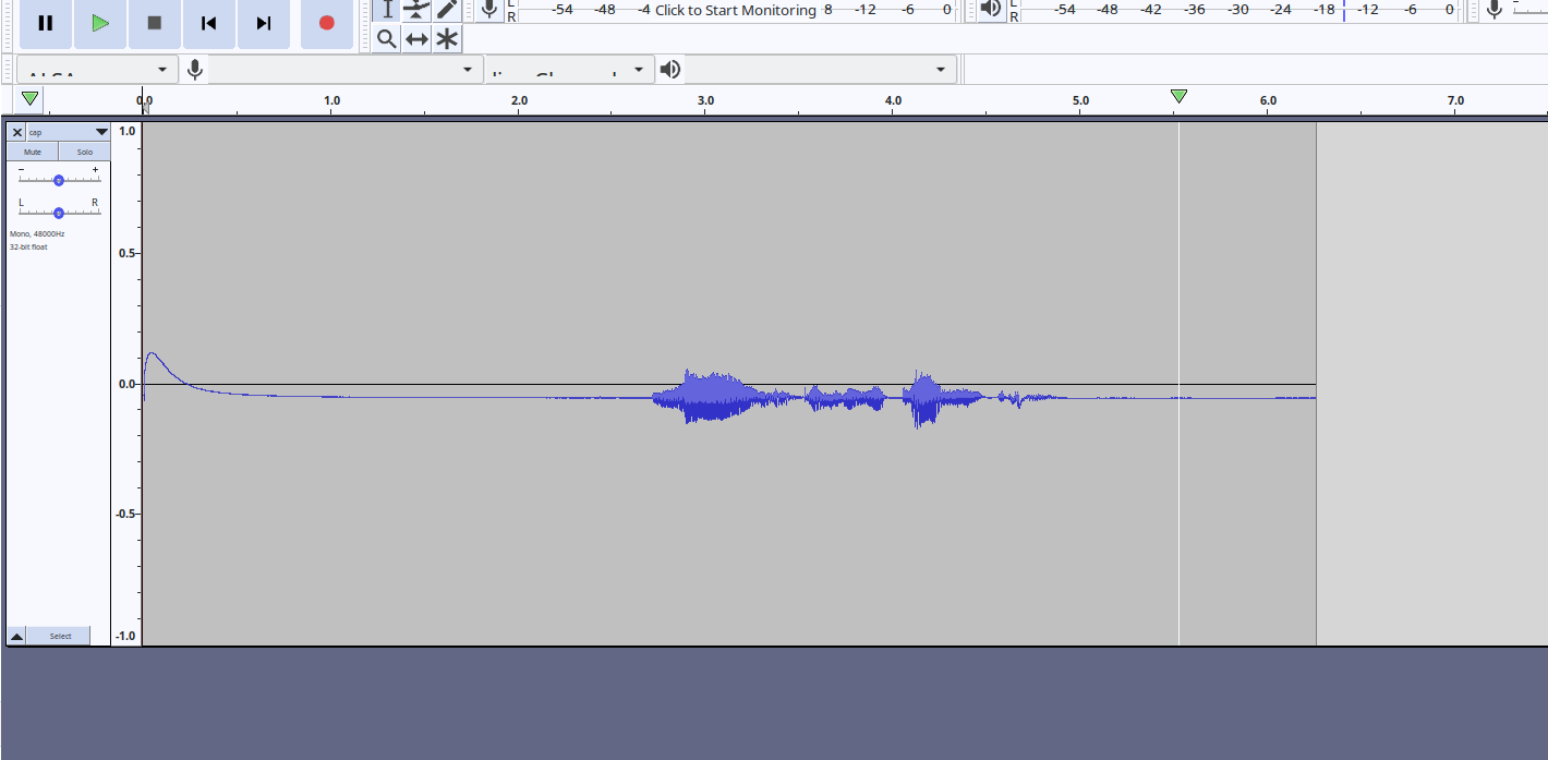
Seems pretty high quality, but a weird click at the start, and some awful DC offset that we can tackle next time.
How to pair bluetooth
To run the robot, you’ll need to get Android Studio and build the App Reward Button for your phone. Once you have that, you’ll need to pair bluetooth:
sudo bluetoothctl
scan on
discoverable on
Now pair your phone on your android
How to provision the NileCAM21
As an alternative option, you can also use a NileCAM21 from e-con systems as a head camera. To get this to work, you’ll need to do the following steps:
- Use the provided driver installation files from the NileCam21/SturdeCAM21 to install a new kernel image, and device tree overlay.
- If you already had run the
jetson-io.pytool, then you’ll need to edit your/boot/extlinux/extlinux.conffile to set the primary boot option to be the default again. (This will load the device-tree provided by the NileCam drivers) - Make a copy of the dtb files in
/boot/dtb - Decompile the e-con systems provided dtb file:
dtc -I dtb -O dts kernel_tegra194-p2888-0001-p2822-0000.dtb > kernel_tegra194-p2888-0001-p2822-0000.dts - You’ll need to manually merge in the pinmux settings for i2s audio on the 40-pin connectors as below.
pinmux@2430000 { pinctrl-0 = <&{/pinmux@2430000/exp-header-pinmux}>; pinctrl-names = "default"; compatible = "nvidia,tegra194-pinmux"; reg = <0x00 0x2430000 0x00 0x17000 0x00 0xc300000 0x00 0x4000>; status = "okay"; phandle = <0x2ae>; exp-header-pinmux { hdr40-pin38 { nvidia,enable-input = <0x01>; nvidia,tristate = <0x01>; nvidia,pull = <0x01>; nvidia,function = "i2s2"; nvidia,pins = "dap2_din_pi1"; }; hdr40-pin35 { nvidia,enable-input = <0x01>; nvidia,tristate = <0x00>; nvidia,pull = <0x01>; nvidia,function = "i2s2"; nvidia,pins = "dap2_fs_pi2"; }; hdr40-pin12 { nvidia,enable-input = <0x01>; nvidia,tristate = <0x00>; nvidia,pull = <0x01>; nvidia,function = "i2s2"; nvidia,pins = "dap2_sclk_ph7"; }; }; - Recompile the dtb file
dtc -O dtb -o kernel_tegra194-p2888-0001-p2822-0000-user.dtb kernel_tegra194-p2888-0001-p2822-0000-user.dts - Make sure the
/boot/extlinux/extlinux.confpoints to your modified dtb.